
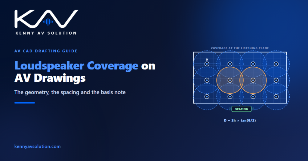
Loudspeaker coverage is the other calculation on an AV drawing that is pure geometry. Like a projector throw, it comes down to a distance, an angle and a bit of trigonometry — and like a projector throw, it is routinely left off the drawing and settled on site by somebody holding a speaker up to the ceiling grid and guessing. The result is a room where the front row is loud, the back corner is not, and nobody can say why.
Acoustic performance targets and the modelling behind them belong to the acoustician or AV designer, working in software built for it. What follows is the layout geometry that lands on the drawing, and the assumptions the drawing has to record. Where a project has an acoustician, their numbers win.
Coverage is geometry before it is acoustics
A loudspeaker is specified with a nominal coverage angle — 90 degrees is the common ceiling speaker figure — which describes the cone within which output stays within a stated tolerance of on-axis, usually measured at a particular frequency band. Outside that cone, level falls away.
What matters for the drawing is where that cone lands. Sound does not arrive at the floor; it arrives at people’s ears. So the surface you care about is the listening plane, conventionally taken at roughly 1.2m above floor for a seated audience and around 1.7m for standing, though you should use whatever figure the project assumes and state it.
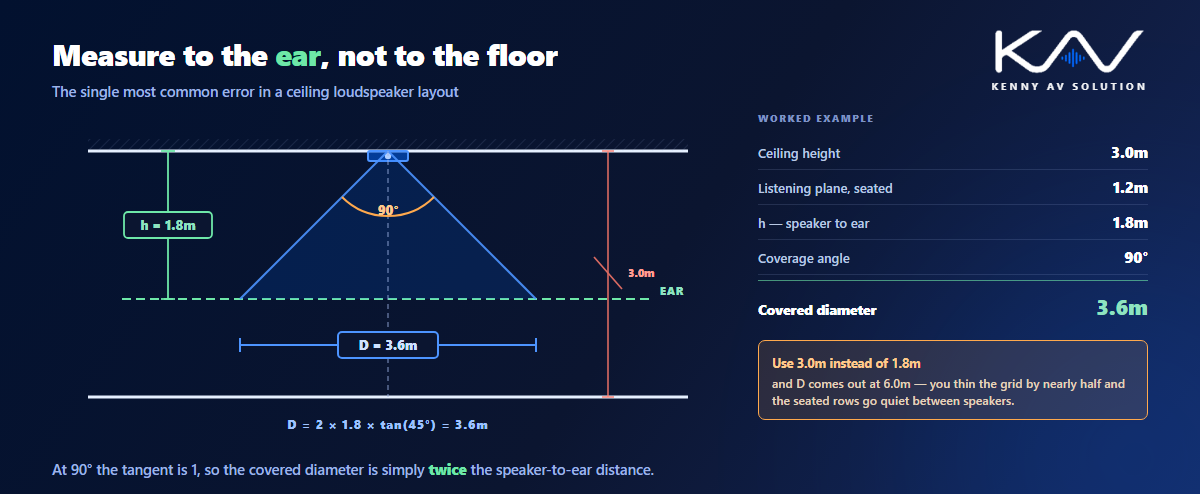
The vertical distance from the loudspeaker to that plane is the number that drives everything. In a room with a 3.0m ceiling and a seated listening plane at 1.2m, it is 1.8m — not 3.0m, and that distinction is the single most common error in the whole exercise.
The calculation, once
For a loudspeaker firing straight down, the diameter of the circle it covers at the listening plane is:
D = 2 × h × tan(θ / 2)
where h is the vertical distance from the loudspeaker to the listening plane and θ is the coverage angle.
Take the room above: h is 1.8m and θ is 90 degrees, so tan(45°) is 1 and D is 3.6m. Each loudspeaker covers a circle 3.6m across at ear height. A 90-degree device is convenient precisely because that tangent is 1 — the covered diameter is simply twice the vertical distance.
Change either input and the answer moves quickly. Raise the ceiling to 4.5m and h becomes 3.3m, so D becomes 6.6m and each loudspeaker covers nearly three times the area. Narrow the device to 60 degrees and tan(30°) is about 0.577, so at the same 1.8m the diameter drops to roughly 2.1m. This is why ceiling height and device selection have to be settled before anybody counts loudspeakers, and why a ceiling height taken from a drawing rather than measured on site can invalidate a whole layout.
Spacing is a decision, not a default
Knowing the covered circle does not tell you the spacing, because you have to decide how much the circles overlap. There are three common patterns, and they are a cost-against-evenness trade rather than a right answer.
Edge to edge. Circles just touch, so spacing equals D. Fewest devices and lowest cost, but level varies noticeably between the point directly under a loudspeaker and the point between two of them. Acceptable for background music and general paging.
Partial overlap. Spacing of roughly seven tenths of D is the usual compromise, tightening the variation considerably for a moderate increase in device count. This is the common choice where speech matters.
Heavy overlap. Spacing at half of D or thereabouts, giving the most even result and the highest cost. Reserved for spaces where intelligibility is critical or contractually measured.
Whichever you use, say which one on the drawing, along with the assumed coverage angle and listening plane. A layout with no stated basis cannot be checked, cannot be value-engineered sensibly, and cannot be defended when somebody asks why there are forty loudspeakers rather than twenty.
The room fights back
Geometry gets you a layout. Whether it sounds any good depends on the room, and on two numbers that are not yours to set.
Reverberation time — usually quoted as RT60, the time for sound to decay by 60 decibels — describes how live the space is. A long reverberation time smears speech, and no loudspeaker layout fixes it. It is why a naturally reverberant space needs tighter coverage and more directional devices than its dimensions alone would suggest, the constraint that dominates worship spaces.
Background noise — commonly expressed as an NC rating — is what the room does when the AV is switched off: ventilation, plant, traffic. If the mechanical design lands noisier than assumed, intelligibility suffers and AV gets blamed for it.
Neither is an AV deliverable, but both are assumptions your layout depends on, so record them on the drawing as stated assumptions. That single note converts a future argument into a documented expectation. Where a project sets a measured speech intelligibility target for acceptance, note that too, because it changes what the system has to achieve rather than merely describing it.
Not every system is a ceiling grid
The circle arithmetic applies to distributed ceiling loudspeakers. Other arrangements need different things on the sheet.
Distributed ceiling. The grid, the spacing basis, and coordination with everything else in the ceiling. Which is the real difficulty: loudspeakers compete with lighting, sprinklers, diffusers and structure, so the layout is settled on the reflected ceiling plan in conversation with the other trades, not drawn in isolation and issued.
Point source on a wall or bracket. Position, mounting height, and — critically — the aiming angle, both horizontally and vertically. An aiming angle is a dimension like any other and belongs on a section. “Aim at the back row” is not a buildable instruction.
Column and line array. Mounting height, splay where applicable, and the vertical coverage the array is set up to produce. These are chosen precisely because they control vertical dispersion in reverberant rooms, so the setup detail is the whole point and should not be left to the installer.
Where the system doubles as life safety, as in the venue case, coverage stops being a comfort question entirely and the layout has to satisfy the fire authority as well as the client.
What belongs on the loudspeaker layout drawing
Somebody should be able to install from it and somebody else should be able to check it. That needs:
- Each loudspeaker positioned and tagged, dimensioned to the ceiling grid or to fixed building features, with tags matching the cable schedule.
- The design basis as a note: coverage angle, listening plane height, spacing pattern, and the ceiling height assumed.
- Coverage circles shown at the listening plane, at least on a representative area, so the overlap is visible rather than asserted.
- Aiming angles for anything not firing straight down, on a section.
- Zone boundaries where the room splits into separately controlled areas, and what each zone is fed from.
- Tap settings where the system is a constant-voltage distributed one, because the installed tap is a design decision and it will otherwise be guessed.
- The acoustic assumptions — reverberation and background noise targets — attributed to whoever set them.
Present it consistently with the rest of the set, following your documented AV drawing standards. The layout is a close cousin of the projector section covered in projector placement: both are geometry that somebody will check with a calculator, so both are worth drawing properly.
Where this goes wrong on site
Three failures account for most of it, and all three are preventable on paper.
The first is measuring from the wrong plane — using floor-to-ceiling height instead of loudspeaker-to-ear height. It inflates the covered diameter and thins the layout, and the symptom is a room that is fine standing and poor seated.
The second is a ceiling that changes after the layout is drawn. A bulkhead appears, a ceiling drops over one end, a coffer is introduced. Coverage assumes a flat plane at a stated height, so any change to that plane invalidates the part of the grid beneath it — which is why the layout belongs in trade coordination rather than issued once and forgotten.
The third is the layout surviving a value-engineering exercise without the basis being revisited. Removing every third loudspeaker from a drawing is easy; it is only obviously wrong if the drawing says what the spacing was supposed to achieve. Teaching and briefing spaces are where this bites hardest, since speech intelligibility is the entire point of the system — the concern running through education AV drawings and, in a more consequential form, courtroom work.
Frequently asked questions
How do you calculate ceiling loudspeaker coverage? Use D = 2 × h × tan(θ/2), where h is the vertical distance from the loudspeaker to the listening plane and θ is the coverage angle. For a 3.0m ceiling with a seated listening plane at 1.2m, h is 1.8m; with a 90-degree loudspeaker, tan(45°) is 1 and the covered diameter is 3.6m.
What height should the listening plane be? Conventionally about 1.2m above finished floor for a seated audience and around 1.7m for standing. The important thing is that the loudspeaker-to-ear distance is used rather than the full ceiling height, and that whichever figure the project assumes is stated on the drawing.
How far apart should ceiling loudspeakers be? It depends on the overlap you choose. Edge to edge means spacing equal to the covered diameter — cheapest, with the most level variation. Roughly seven tenths of the diameter is the common compromise where speech matters. Around half the diameter gives the most even coverage at the highest cost. State which pattern the layout uses.
Do RT60 and NC ratings belong on an AV drawing? Not as AV deliverables — they are set by the acoustician and the mechanical design. But they are assumptions the layout depends on, so record them as stated assumptions attributed to whoever set them. If the room turns out livelier or noisier than assumed, that note is what distinguishes a design that was wrong from one whose premises changed.
What does a higher ceiling do to the loudspeaker count? It reduces it, because the covered diameter grows with the distance to the listening plane. Raising a 3.0m ceiling to 4.5m takes h from 1.8m to 3.3m and the covered diameter from 3.6m to 6.6m with a 90-degree device. The trade is that taller, livelier rooms usually need more directional loudspeakers, so the saving is rarely as large as the geometry alone suggests.
Need loudspeaker layouts and coverage drawn?
Kenny AV Solution produces AV drawing sets in AutoCAD for integrators, consultants and contractors worldwide — loudspeaker layouts with coverage shown and the design basis noted, reflected ceiling plans coordinated with the other trades, projector sections, rack elevations with power and heat schedules, containment routing, cable schedules and as-builts, drawn to your standards and your title block. Send us the room, the ceiling height and the device you intend to use, and we will draw the coverage and tell you where the grid does not work. See our AV CAD drafting services, grab the free AV CAD Drafting Standards Checklist, or schedule a quick call — we come back with a quote and timeline within one business day. For the underlying documentation standards, AVIXA is the reference worth having on the shelf.