
Projector placement is one of the few things on an AV drawing that is genuinely arithmetic. Everything else involves judgement: where a loudspeaker sounds right, how a rack should be ordered, which detail a joiner will actually read. A projector position is a calculation, and it is wrong or it is right. Which makes it all the more irritating that it is one of the most common things to get wrong on site, usually because the number was never on the drawing in the first place.
Throw ratio is the whole calculation
A projector’s throw ratio is the relationship between how far it sits from the surface and how wide an image it produces. It is quoted as a ratio — 1.5:1, or 0.8:1 for a short throw — and it means throw distance divided by image width.
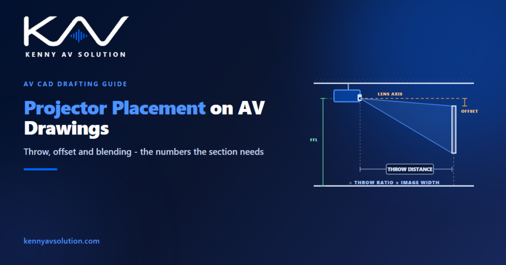
So the arithmetic runs one way: throw distance = throw ratio × image width. A 1.5:1 lens producing a 4.0m wide image has to sit 6.0m from the screen. Turn it round when the room is fixed: a projector that can only be 5.0m back, producing that same 4.0m image, needs a 1.25:1 lens or shorter.
Most projectors have zoom lenses, so the ratio is a range rather than a single figure — 1.4 to 2.1:1, say. That range is your design tolerance, and it is worth stating on the drawing rather than assuming. If your calculated position sits at the extreme end of the range, you have no adjustment left on site, and site always wants some.
Note also that throw ratio is specified against image width, not the diagonal that screens are usually sold by. Mixing the two is a reliable way to end up a metre out. The image size itself should come from the farthest viewer and the content on screen; see AV display sizing with DISCAS.
Lens offset decides the mount height
This is the part that gets skipped, and it is why so many projectors end up shimmed, tilted or hung at a height nobody can explain.
A projector does not put its image on the lens centreline. It projects with a vertical offset, quoted as a percentage of image height. At 100% offset the whole image sits above or below the lens axis; at 0% it is centred on it. Ceiling-mounted projectors are usually inverted, so the offset throws the image downward from the lens.
The consequence is simple and frequently ignored: the offset, not the screen, sets the mount height. Work from the top of the image, apply the offset, and that is where the lens has to be. Then add the mount drop and you have the fixing height for the structure above. Put that dimension on the drawing as a figure from finished floor level, not as “ceiling mounted”.
Where the projector has lens shift, the offset becomes adjustable within a stated range, which is a genuine design margin. Lens shift is optical and costs you nothing. It is worth confirming what range the chosen model actually has, because it varies enormously and the cheap end of the market often has none at all.
Where the projector physically goes
A calculated position is only useful if something can actually be mounted there and the light can get to the screen.
Check the structure first. A ceiling-mounted projector hangs from whatever is above the ceiling, not from the ceiling itself, so you need to know what is up there and whether it can take the load — which is exactly what a proper site survey is for, and why the void matters more than the tile. Where backing or secondary steel is needed, it belongs in somebody else’s package well before you need it, as with any other trade interface.
Then check the light path. The throw cone has to be clear of lighting fixtures, sprinkler heads, HVAC diffusers, ceiling fans, signage and structure. This is a coordination exercise on the reflected ceiling plan, not something to discover at second fix — and it is the single most common reason a projector position moves late in a job.
Finally, check for people. Anyone presenting in front of a long-throw projector will stand in the beam, cast a shadow and be dazzled. If the room’s use puts a presenter at the screen, that is an argument for a shorter throw, a different position, or a different display technology entirely. Say so on the drawing rather than leaving it for the room to discover.
Keystone correction is not a fix
If the geometry does not work, the temptation is to tilt the projector and correct digitally. It is worth being clear about what that costs.
Keystone correction is a digital transform. It scales and reshapes the image inside the panel, so you lose real pixels and some sharpness, and it does nothing about focus — a tilted projector has a projection surface at varying distances, so parts of the image will be softer than others. It is a recovery tool, not a design decision.
The order of preference is: get the position geometrically right; use lens shift to accommodate what is left; and only then accept a small keystone correction. If a design needs significant keystone to work, the position is wrong and the drawing should say so while it is still cheap to change.
Edge blending changes the arithmetic
Where one projector cannot cover the surface — a wide canvas, a curved wall, a mapped surface — two or more are overlapped and blended, and the geometry gets a second layer.
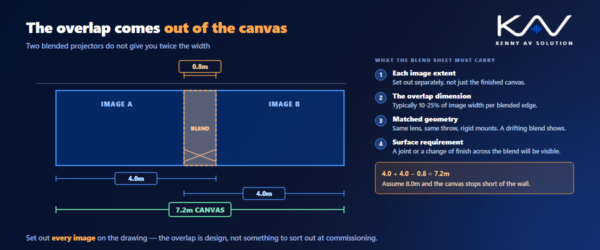
In a blend, adjacent images overlap by a region in which both projectors contribute, each ramped down so the combined brightness stays even. The overlap is typically something like 10 to 25 percent of image width per edge, depending on the processor and the content. That overlap is not free canvas: it is subtracted from the total.
So for two projectors each producing a 4.0m image with a 0.8m overlap, the finished canvas is 4.0 + 4.0 − 0.8 = 7.2m, not 8.0m. Miss that and the canvas does not reach the ends of the wall. Set it out properly on the drawing: each projector position, each image extent, the overlap dimension, and the resulting total.
Blending also tightens everything else. Both projectors need the same throw geometry and the same lens, the surface has to be consistent across the join, and the mounting has to be rigid, because a blend that drifts is more obvious than no blend at all. State the surface requirement on the drawing — blending onto a wall with a visible joint or a change of finish will show.
Brightness and the things a drawing cannot fix
Brightness sits at the boundary of drafting. Sizing a projector in lumens for a given image size, screen gain and ambient condition is the designer’s job, informed by manufacturers’ data. What the drawing can and should do is record the assumption.
State the ambient light condition the design assumes, because that assumption is what gets broken. A projector specified for a room with controlled lighting will disappoint in the same room with the blinds up, and the drawing is the only place that expectation is written down. Where there is a rooflight, a glazed wall or a west-facing window, note it — the constraint that dominates worship spaces and many teaching rooms.
The related point is that a screen is a specified item, not a white wall. Surface, gain and viewing angle all change the result, and where the design assumes a particular screen, the drawing should name it rather than implying it.
What belongs on a projector placement drawing
The set should let somebody install the projector without phoning anyone. In practice:
- Position on plan, dimensioned to fixed building features rather than to furniture or ceiling tiles.
- A section through the throw path, showing the lens height from finished floor, the screen top and bottom, and the throw distance as a dimension.
- Throw distance and image width, with the lens range that satisfies them, so a substitution can be checked.
- Mount type and drop length, and what it fixes to — with the structural requirement stated where one exists.
- Power and data at the projector position, routed and shown on the containment drawings like anything else.
- Service access for filters, lamps where applicable, and the eventual replacement of the unit itself.
- For blends: each image extent, the overlap dimension, the resulting canvas, and the surface requirement.
Keep the device tags consistent with the cable schedule and the rest of the set, and follow your documented AV drawing standards for how the section is presented. A projector section is one of the few AV drawings a non-AV reader will genuinely try to interpret, so it is worth drawing clearly. Getting it wrong is also one of the classic mistakes in AV construction drawings.
Frequently asked questions
How do you calculate projector throw distance? Multiply the throw ratio by the image width. A 1.5:1 lens producing a 4.0m wide image needs 6.0m of throw. Note that throw ratio is quoted against image width, not the diagonal screens are usually sold by, and that zoom lenses give a range rather than a single figure.
What does projector lens offset mean? It is how far the projected image sits above or below the lens centreline, given as a percentage of image height. It is what actually determines the mount height: work from the top of the image, apply the offset to find the lens position, then add the mount drop to get the fixing height. Lens shift, where available, makes that offset adjustable optically.
Is keystone correction acceptable? As a small final adjustment, yes. As a design solution, no. It is a digital transform that discards real pixels and softens the image, and it cannot fix the focus variation caused by a tilted projector facing a flat surface. Solve the geometry first, use lens shift next, and treat keystone as a last resort.
How much overlap does edge blending need? Typically in the region of 10 to 25 percent of image width per blended edge, depending on the processor and content. That overlap comes out of the total canvas: two 4.0m images overlapped by 0.8m produce 7.2m, not 8.0m. Confirm the figure with the processor manufacturer and set it out on the drawing.
What should a projector position drawing show? The position dimensioned on plan to fixed building features, a section through the throw path with lens height above finished floor and the throw distance dimensioned, the image width and lens range, the mount type and what it fixes to, power and data provision, and service access.
Need projector sections and setting-out drawn?
Kenny AV Solution produces AV drawing sets in AutoCAD for integrators, consultants and contractors worldwide — projector position plans and throw sections, blend setting-out, screen and display elevations, rack elevations with power and heat schedules, containment routing, cable schedules and as-builts, drawn to your standards and your title block. Send us the room, the image size and the projector you intend to use, and we will draw the geometry and flag where it does not work. See our AV CAD drafting services, grab the free AV CAD Drafting Standards Checklist, or schedule a quick call — we come back with a quote and timeline within one business day. For the underlying documentation standards, AVIXA is the reference worth having on the shelf.