
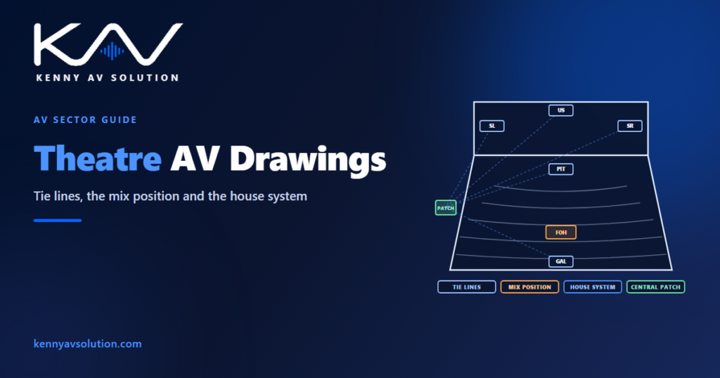
Theatre AV drawings — for theatres, concert halls, school auditoriums and performing arts centres — document a building where the most important equipment arrives with each show and leaves when it closes. Touring productions bring their own consoles, microphones and often loudspeakers; resident companies change their setup with every production. What the building keeps is the infrastructure: the house loudspeaker system, the tie lines that connect the stage to the mix position and the racks, the stage management systems and the containment that lets equipment be plugged in wherever the show needs it. Theatre AV drawings are mostly about that infrastructure.
Performing arts buildings usually have a theatre consultant, and their brief, the rigging and structural design, and the local code govern. Products and connector standards vary. What follows is common practice for the AV share of the work.
House system and production system
Separate the two from the start. The house system belongs to the building: the main loudspeaker arrays, fills and delays, the infrastructure, the stage management systems and the show relay. The production system belongs to the show: the mixing console, radio microphones, effects and anything a touring company brings. The drawings should make it obvious where one ends and the other begins, usually at a set of patch points or network ports, and the responsibility matrix should say who supplies and maintains each side.
Tie lines are the backbone
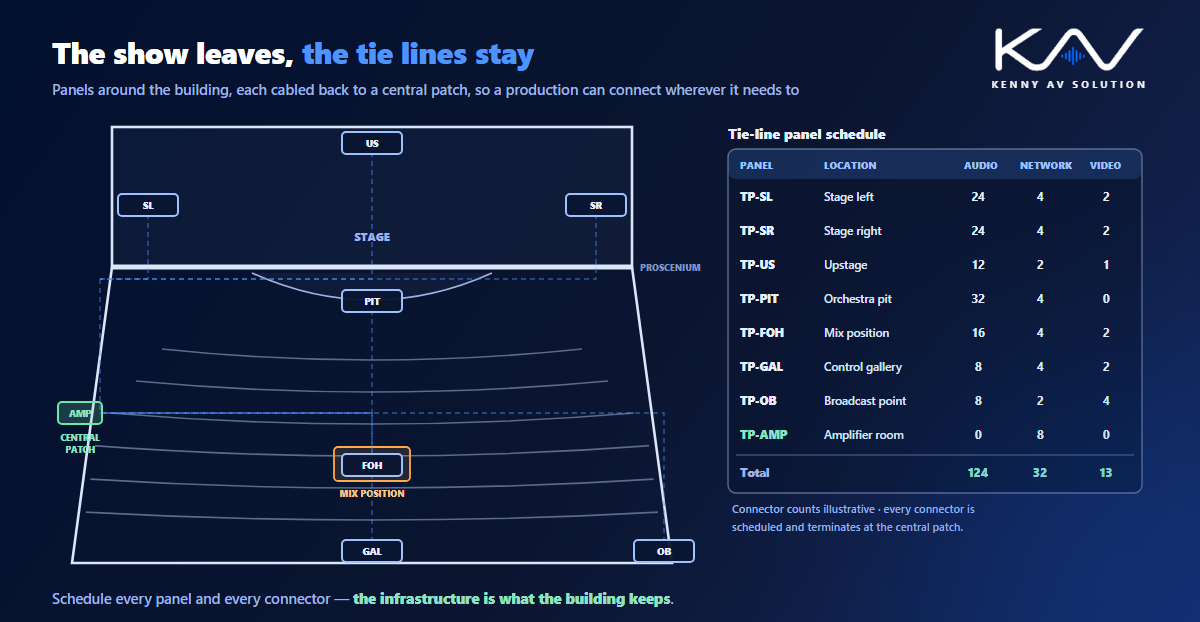
Almost every theatre AV problem is a connection problem: the show needs a microphone in the orchestra pit, a loudspeaker on the balcony rail or a feed to the broadcast truck, and the question is whether there is a way to get it there. The answer is the tie-line system — panels around the building, connected back to central racks, carrying analogue audio, network audio, video and data.
Typical panel locations include stage left and right, upstage, the orchestra pit, the mix position, the lighting and sound galleries, the amplifier room and the broadcast or outside-broadcast connection. Draw each panel on the plan, give it a tag, and schedule every connector on it: type, quantity and where it terminates. The cable schedule then carries every run between panels, and the patch bay or network switch at the centre is shown on the rack elevation.
The mix position
The sound engineer needs to hear what the audience hears, which is why the mix position is usually in the audience area, not in a booth behind glass. Its location affects seating, sightlines and ticket revenue, so it is often a negotiation. Draw it with its footprint, the seats it removes, its tie-line panel and power, and the containment back to the racks. Many buildings also provide a second position for touring consoles, or a removable riser that can be replaced with seats when it is not needed.
Loudspeakers and rigging
Main arrays, fills and delays are drawn on plan and section with their coverage, the same way as in loudspeaker coverage drawings. In a theatre they also have to be coordinated with the proscenium, the fly tower, lighting positions and the stage machinery. Rigging points, hoists and their loads are designed by the rigging engineer; the AV drawings show the loudspeaker positions, weights and trim heights the rigging has to support.
Stage management systems
Theatres run on communication. The stage manager’s desk, usually at the side of the stage, connects to the production intercom, the show relay and paging to dressing rooms and backstage areas, cue lights, and video of the stage for performers and crew waiting to go on. Each is a small system with outstations around the building, and each needs positions, cabling and power on the drawings. Show relay and backstage paging follow the same zoning principles as any paging system.
What the drawing set contains
- Plans and sections with house loudspeakers, coverage, the mix position and tie-line panel locations.
- A tie-line panel schedule listing every panel and connector, and where it terminates.
- Rack elevations for the central patch, amplifiers and processing.
- Stage management systems: the stage manager’s desk, intercom, show relay, paging and cue light outstations.
- Signal flow for the house system and the interfaces to the production system.
- Assistive listening coverage for the audience, as covered in assistive listening drawings.
Frequently asked questions
What is a tie-line system in a theatre? A network of connection panels around the building — on stage, in the orchestra pit, at the mix position, in the galleries and the amplifier room — cabled back to central racks, so audio, video and data can be connected wherever a production needs them.
What is the difference between a house system and a production system? The house system belongs to the building: main loudspeakers, infrastructure and stage management systems. The production system belongs to the show, such as the mixing console and radio microphones, and changes with each production.
Where should the mix position be in a theatre? Usually in the audience area, so the engineer hears what the audience hears. Its location, footprint and the seats it removes should be agreed early and shown on the drawings.
What are stage management systems? The communication systems a show runs on: production intercom, show relay to backstage areas, paging, cue lights and stage video, usually controlled from the stage manager’s desk.
Who designs theatre rigging for loudspeakers? The rigging or structural engineer, usually working with the theatre consultant. The AV drawings provide loudspeaker positions, weights and trim heights for the rigging design.
Need theatre AV drawings?
Kenny AV Solution drafts AV documentation for integrators, consultants and design-build teams worldwide — tie-line panel schedules, loudspeaker plans and sections, mix position details, stage management systems, rack elevations and signal flow, all drawn to your standards and your title block. See our drafting services, get an existing set checked with a drawing set review, or schedule a quick call — we come back with a quote and timeline within one business day.