
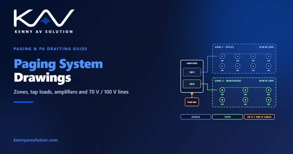
Paging system drawings often look finished as soon as the loudspeakers are on the reflected ceiling plan. But a paging and background music system is a distribution system: loudspeakers hang off long cable runs from amplifiers in a rack, grouped into zones, with power, losses and priorities that all need numbers. The plan shows where the sound comes from. The rest of the drawings show whether it will actually arrive — loud enough, in the right zone, and over the music when it matters.
Life-safety voice alarm and voice evacuation systems are governed by their own standards — for example EN 54 and BS 5839-8 in Europe and the UK, or NFPA 72 in the United States — and are designed and certified as part of the fire strategy. A general paging system must not be relied on for evacuation unless it has been designed and approved for that purpose. The figures below are illustrative; the manufacturer’s data and the designer govern.
Constant-voltage lines: how paging is wired
Most paging and background music systems use constant-voltage loudspeaker lines: 70 V is common in North America and 100 V in Europe and many other regions. Each loudspeaker has a small transformer with several power taps — for example 1, 2, 4 or 8 W — and the tap chosen sets how loud that loudspeaker plays. Many loudspeakers can then be wired in parallel along one line from a single amplifier channel.
The load on a line is simply the sum of the tap settings of every loudspeaker on it. That makes the arithmetic easy, but only if the taps are on the drawings. Show the tap at every loudspeaker on the plan or in the schedule, because the installer sets them by hand and the commissioning engineer needs to check them.
Zones: decide what must be announced separately
A zone is a group of loudspeakers that always plays the same thing. Zones follow how the building is used: a page for the warehouse should not interrupt the boardroom, and background music in the restaurant may need its own volume. Agree the zones with the client, then show them on the plan as coloured outlines or tags, and list them in a zone schedule: zone name, loudspeakers, total tap load, amplifier channel and the sources it can hear.
Keep the zone names identical across the plans, the schedule, the signal flow diagram and the paging station buttons, so a page to “Loading Dock” reaches the loading dock.
Size each amplifier channel from the taps
Add up the taps in each zone and choose an amplifier channel with headroom above that total. Allowing around 20 to 25 percent is common practice: a zone with 120 W of taps would get a channel of at least 150 W. Without the margin, the amplifier runs at its limit and the system has no room for a loudspeaker added later.
Show the totals on the drawings, zone by zone. Amplifier power also becomes heat in the rack, so carry the amplifier figures into the rack power and heat load.
Check the cable loss before choosing the cable
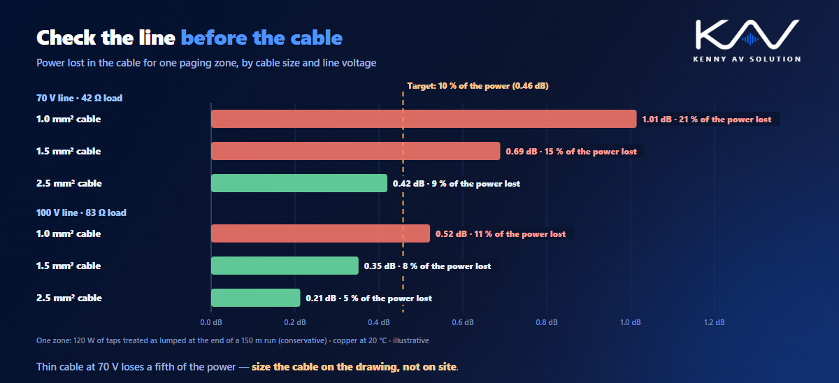
Long loudspeaker runs lose power in the cable. The loss depends on the run length, the cable size, the line voltage and the load. A common design target is to lose no more than about 10 percent of the power, roughly 0.5 dB. A simple, conservative check treats the whole zone load as if it sat at the far end of the run.
In the illustrative zone below, 120 W of taps at the end of a 150 m run loses about 1 dB on 1.0 mm² cable at 70 V — around a fifth of the power. Heavier cable, a 100 V line, a shorter run or splitting the zone each bring it back under the target. The choice belongs on the drawings and in the cable schedule, not on site.
Priorities and interfaces
Paging systems handle several sources at once — paging microphones, background music, pre-recorded messages — so they need a priority order: typically emergency messages over live pages, and live pages over music. Write the order down and show the sources, the zone selection and the priorities on the signal flow diagram.
Where the fire alarm must mute the music or the paging, draw the interface on both the paging and the fire alarm drawings, and record who provides it in the responsibility matrix. Paging stations and volume controls belong on the wall elevations with their heights.
Intelligibility, not just loudness
A page has to be understood, not just heard. Loudspeaker spacing, mounting height and the room’s acoustics decide that, so lay the loudspeakers out from their coverage, as in loudspeaker coverage drawings, rather than one per ceiling tile. Speech intelligibility can be measured as a speech transmission index (STI), usually with the STIPA method, and checked at commissioning against the target agreed for the project.
What a paging drawing set contains
- Loudspeaker plans with every loudspeaker, its tap setting and its zone.
- A zone schedule with loudspeakers, total tap load, amplifier channel and sources.
- Amplifier sizing with the headroom stated, carried into the rack power and heat load.
- Cable loss checks for long runs, with the cable size chosen.
- Signal flow with sources, zone routing and the priority order.
- Interface details with the fire alarm, drawn on both sides.
- Rack elevations and paging station details.
Hotels, hospitals, airports and stadiums lean on paging most heavily; see the hotel, healthcare and airport guides for how the zoning changes by building type.
Frequently asked questions
What is a 70 V or 100 V loudspeaker system? A constant-voltage system in which many loudspeakers, each with a transformer and selectable power taps, are wired in parallel on one line from an amplifier. 70 V is common in North America and 100 V in Europe and many other regions. The load on the line is the sum of the tap settings.
How do you size an amplifier for a paging zone? Add up the power taps of every loudspeaker in the zone and choose an amplifier channel with headroom above that total, commonly around 20 to 25 percent. A zone with 120 W of taps would need a channel of at least 150 W.
How much cable loss is acceptable on a loudspeaker line? A common design target is no more than about 10 percent of the power, roughly 0.5 dB. Loss rises with run length and load, and falls with heavier cable or a higher line voltage, so long runs should be checked before the cable size is chosen.
What is the difference between 70 V and 100 V systems? The line voltage. For the same load, a 100 V line carries less current than a 70 V line, so it loses less power in the same cable. Which one is used is mostly a matter of regional practice and the equipment available.
Can a paging system be used for emergency evacuation? Only if it has been designed, installed and certified as a voice alarm or emergency communication system under the standards that apply, as part of the fire strategy. A general paging and background music system should not be relied on for evacuation.
Need paging system drawings?
Kenny AV Solution drafts AV documentation for integrators and consultants worldwide — loudspeaker plans with taps and zones, zone schedules, amplifier and cable loss calculations, signal flow and rack elevations, drawn to your standards and your title block. Send us the floor plans and the zoning requirements. See our drafting services, grab the free AV CAD Drafting Standards Checklist, or schedule a quick call — we come back with a quote and timeline within one business day.