
AV commissioning is the point where the system meets the documents. Every check asks the same question — does it do what it should? — and “should” has to be written down somewhere. If the expected result is not on the drawings or in the specification, verification turns into opinion: the installer says it works, the client says it doesn’t, and nobody can point to the page that settles it.
Electrical testing, fire alarm interfaces and emergency voice systems are verified by their own trades and the authority having jurisdiction under their own rules. What follows covers the AV system and the documentation that makes it verifiable.
What ANSI/AVIXA 10:2013 actually gives you
The reference standard is ANSI/AVIXA 10:2013, Audiovisual Systems Performance Verification, first published by InfoComm before the association became AVIXA. It is often misunderstood in two directions.
It does not tell you how well a system must perform. There is no single loudness, image size or latency figure in it that every project has to hit. What it gives you is a structured list of reference verification items and a process for using them: agree which items apply to this project, how each one will be checked, what counts as a pass, and how the results are recorded.
It organises verification into four phases — pre-integration, systems integration, post-integration and closeout — so that checks happen when they are cheapest to act on. A wrong backbox found before the wall is boarded costs minutes; the same fault found at handover costs a patch, a repaint and a day.
The targets themselves come from the project, and often from other standards. Coverage uniformity can be specified against ANSI/AVIXA A102.01, image size against ANSI/AVIXA V202.01, labelling against ANSI/AVIXA F501.01. The verification list is where those targets are tied to specific rooms, devices and methods.
Choose the checks when you draw, not when you test
The most useful verification decisions are made at design, not in the last week on site.
Treat the verification list as a design document. For each item it should state the phase, the method, the pass criterion, who performs the check and what evidence is kept — a measurement, a photo, a signed sheet. Issued with the drawings, it tells the integrator what will be checked before they price the job, which is far fairer than discovering the acceptance criteria at the end.
On a consultant-led project the list belongs in the specification; on a design-build project the integrator writes it as part of their own submittal. The difference between those routes is covered in design-build vs bid-spec. Either way, it should exist before installation starts.
Every drawing is a test sheet in waiting
A good drawing set already contains most of the verification plan. It simply has not been read that way yet.
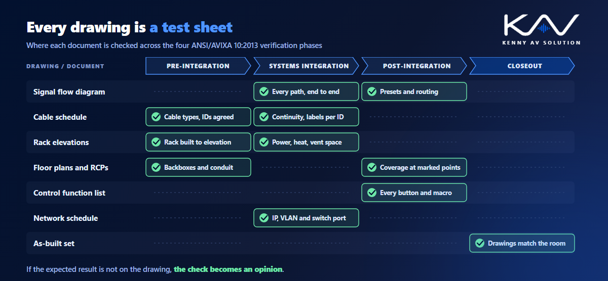
- The signal flow diagram defines every path to test end to end: each source to each destination it is meant to reach, through every switcher, processor and extender in between.
- The cable schedule is the continuity and labelling checklist. Every cable ID gets tested, and the label at each end is checked against the schedule.
- The rack elevations are checked against the built rack: positions, vent space, cable management, and the power and heat figures they were designed around.
- The floor plans and reflected ceiling plans confirm device locations and mounting heights, and they are where the measurement positions for coverage and sightline checks should be marked.
- The control function list becomes a button-by-button test: every page, every macro, every preset, including the shutdown sequence.
- The network documentation — IP schedule, VLANs, switch ports — is verified device by device, as described in AV over IP network diagrams.
Laid out against the four phases, the drawings and the checks line up almost exactly.
Write the expected result where the tester will look
A verification item is only as strong as its pass criterion. “Verify audio is acceptable” is not a test. “Speech level at each marked listener position within the coverage tolerance stated in the basis note” is.
That means the drawings have to carry the expected values, not just the equipment:
- The coverage basis note — target, spacing method and listener height — on the ceiling plan, as described in loudspeaker coverage on AV drawings.
- The image size and viewing distances on the projection or display section, as in projector placement.
- The routing and preset intent on the signal flow: which inputs each room can select, which outputs follow which source.
- The IP addresses and VLANs on the network schedule, so “on the network” can be checked against a specific value.
Avoid notes that push the decision onto the tester, such as “set to suit” or “adjust on site”. If a value really can only be set on site, say so, and say where the final value is recorded, so it ends up in the closeout documents rather than in someone’s memory.
Record results against tags and cable IDs
The fastest way to make verification traceable is to use the identifiers that are already on the drawings.
Test sheets should be keyed to the same device tags and cable IDs as the drawings and the schedules. A result then reads “cable 1204-SW1-RX2: continuity pass, labels both ends match” rather than “display cable in room 1204 checked”. When something fails, the punch list item carries the same ID, the fix is re-tested against the same line, and anyone can follow the trail later. A consistent scheme across the set, set out in your AV drawing standards, is what makes this possible.
Some checks change the design rather than confirming it: a loudspeaker moved to clear a sprinkler head, a cable rerouted, a preset added at the client’s request. Those go back onto the redlines and into the as-built drawings. Verification and as-builts are two halves of the same job: one proves what the system does, the other records what was built.
Closeout: the documents get verified too
Documentation is itself something to verify, not just something to hand over.
At closeout, check that the as-built drawings reflect the final installation, that the labels in the field match the cable schedule, that the revision on every sheet is the issued one, and that configuration files and passwords have been handed to the owner in the agreed way. Revision discipline matters here; see AV drawing revision control. The verification report then becomes part of the record: what was checked, when, by whom, and against which version of the documents. The full handover package is covered in AV closeout documentation.
That record is what a service technician, the next integrator or the owner’s IT team will rely on years later. A system with a clean verification record and accurate as-builts is a system somebody else can safely maintain.
What a verification-ready drawing set contains
- A verification list with phase, method, pass criterion, responsibility and evidence for each item.
- Signal flow diagrams complete enough to define every end-to-end path.
- A cable schedule with unique IDs that match the labels in the field.
- Rack elevations with power and heat totals.
- Floor plans and RCPs with mounting heights and marked measurement positions.
- Basis notes stating the coverage, image size and other performance targets.
- A control function list written as testable steps.
- A network schedule with IP addresses, VLANs and switch ports.
- Test sheets keyed to device tags and cable IDs, feeding the punch list and the as-builts.
For the underlying standards, AVIXA publishes 10:2013 and the related performance standards.
Frequently asked questions
What is ANSI/AVIXA 10:2013? It is the AV industry standard for performance verification, originally published by InfoComm. It provides a structured list of reference verification items and a process for selecting the ones that apply to a project, defining how each is checked and what counts as a pass, and recording the results. It organises verification into pre-integration, systems integration, post-integration and closeout phases.
Does ANSI/AVIXA 10:2013 set performance targets? No. It defines what to check and how to manage the process, not how well a system must perform. The targets come from the project documents, often by reference to other standards such as ANSI/AVIXA A102.01 for audio coverage uniformity or ANSI/AVIXA V202.01 for display image size.
What is the difference between AV commissioning and performance verification? The terms are often used loosely. Commissioning usually means bringing the system into operation — configuring, adjusting and tuning it. Performance verification is the documented process of proving that it meets the agreed criteria, item by item, with recorded results.
Which drawings are used during AV verification? Most of the set. The signal flow defines the paths to test, the cable schedule is the continuity and labelling checklist, the rack elevations are checked against the built racks, the floor plans and reflected ceiling plans confirm locations and measurement positions, and the control function list and network schedule are verified item by item.
What happens when a verification check fails? The failure goes on the punch list under the same device tag or cable ID used on the drawings, is fixed and re-tested against the same item. If the fix changes the design — a moved device or a rerouted cable — it is marked on the redlines and carried into the as-built drawings.
Need a verification-ready AV drawing set?
Kenny AV Solution produces AV drawing sets in AutoCAD for integrators and consultants worldwide — signal flow diagrams, rack elevations, floor plans and RCPs, cable schedules, network schedules and as-builts, with the tags, cable IDs and basis notes that verification depends on. Send us your design and equipment list, and we will produce a set your team can install, test and hand over from. See our AV CAD drafting services, grab the free AV CAD Drafting Standards Checklist, or schedule a quick call — we come back with a quote and timeline within one business day.