
AV wall elevations are the drawings that get built before the equipment exists. The wall is framed, the blocking goes in, the backboxes are set and the drywall closes — often months before anyone unboxes the display. When the display finally goes up, it lands wherever the blocking and the boxes allow, not wherever the design intended. The elevation is the only chance to make those two places the same.
Whether a wall or ceiling can carry a heavy load is for the structural engineer to confirm, and accessibility rules vary by jurisdiction. The accessibility figures below are from the 2010 ADA Standards for Accessible Design in the United States and are given as an example; check what applies to your project.
Dimension from things that exist at rough-in
An elevation is read by trades who arrive long before the AV equipment. Every dimension has to point at something that is already there when they read it.
Vertical dimensions start from a stated datum, normally above finished floor (AFF). Say which floor that is. On a raised access floor, over a thick screed, or where carpet and underlay are still to come, “finished floor” is not the slab the framer is standing on, and a 2 in difference is enough to put a touch panel out of reach.
Horizontal dimensions should run from fixed building features — a wall end, a gridline, a door jamb, a column face — not from the display, which does not exist yet. Dimension to the finished face of walls, and say so, because the framer will otherwise measure from the stud. The base drawing behind your elevation matters too; see working with architectural backgrounds.
Say which point of the display you mean
“Display at 60 in AFF” is not a dimension. It could mean the centre of the screen, the bottom of the bezel or the top of the mount, and on a 75-inch display the centre and the bottom edge alone are about 18 in apart.
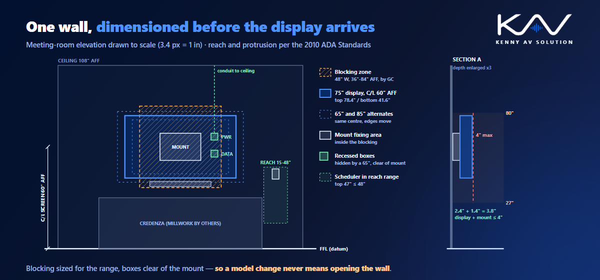
State the reference point every time: centre of screen, bottom of display or top of display. Centre of screen is usually the most robust choice, because it survives a change of model: if a 75-inch display becomes an 85-inch one, the centre can stay put while the edges move. Give the expected screen dimensions alongside it so the other trades can see the edges, and note an allowed tolerance.
The same applies to everything positioned relative to the screen. A camera or video bar is dimensioned from the screen edge it sits against — “video bar centred on display, 2 in below bottom edge” — so that it moves with the display rather than being stranded by a model change. Sightline and viewing-distance checks belong on the plan and section; for projected images, the geometry is covered in projector placement on AV drawings.
Blocking is sized for the range, not the model
Blocking — the timber, plywood or steel built into the wall for the mount to fix into — is installed by the general contractor, long before the mount arrives. Once the wall is boarded, adding it means opening the wall.
So size it for the range of what might be mounted, not for the one mount in the current specification. Show the blocking zone as a hatched area with its width and its top and bottom heights AFF, comfortably larger than the mount’s fixing pattern, so that a different mount, a larger display or a revised height can still find solid fixing. Note the material, the wall construction it sits in, and the load it has to carry: display and mount weight together, plus any articulating arm, which multiplies the load at the fixings.
Who provides it has to be written down, not assumed. That split is part of AV trade coordination. Anything heavy, overhead or on an unusual wall goes to the structural engineer with the weights stated; see the mounting detail requirements in AV drawings for permit and inspection.
Backboxes go behind the display — but not behind the mount
The power and signal boxes for a wall display want to be hidden behind it. The common failure is putting them exactly where the mount plate goes.
Position recessed boxes inside the display’s outline but clear of the mount’s fixing area, at a height where the cables reach the display’s inputs without strain. Dimension each box to the same datum and fixed features as everything else, and state what it is: a recessed power box, a data box, a signal box. Where the display might change size, place the boxes where they stay hidden behind the smallest likely screen.
Show the conduit or pathway from each box up into the ceiling void or down to the floor, with its size, so the electrician and the AV installer are pulling to the same place. The pathway itself is described in AV conduit and riser diagrams.
Reach, protrusion and people walking past
Two accessibility rules shape most AV elevations, and both are easy to put on the drawing.
The first is reach range. Under the 2010 ADA Standards, operable parts that people need to use — touch panels, room schedulers, wall plates the user connects to — generally fall within an unobstructed reach range of 15 in minimum to 48 in maximum above the floor. Dimension the operable part, not the backbox behind it, and check it against the range on the elevation itself.
The second is protruding objects. In a circulation path, an object whose leading edge is between 27 in and 80 in above the floor may protrude no more than 4 in from the wall. A wall display in a corridor or lobby usually falls inside that band, so the elevation needs a section showing the total depth of display plus mount, and a low-profile or recessed mount where the depth would exceed it. Courtrooms and public buildings bring their own requirements on top; see courtroom AV drawings.
Millwork, furniture and everything else on the wall
A wall elevation is also a coordination drawing, because the display is rarely alone on the wall.
Show the credenza or millwork below the display with its top height, so the bottom of the display clears it and the cables have somewhere to go. Show light switches, thermostats, fire alarm devices and outlets by others where they share the wall, so that a thermostat does not end up behind the screen. In a meeting room, the camera position on the elevation and the seating on the plan should tell the same story; the room-level view is in corporate AV design documentation.
Large multi-display walls are a step beyond this, dimensioned to the individual panel; that level of detail is covered in control room AV drawings. For signage estates with many repeated positions, a typical elevation with a schedule of variations is more practical than one drawing per screen, as described in digital signage AV drawings.
What a good AV elevation sheet contains
- A stated datum — finished floor level, with the finish noted where it is not yet installed.
- Horizontal dimensions from wall ends, gridlines or jambs to finished faces.
- Display position by a named reference point — centre, bottom or top — with screen dimensions and tolerance.
- The blocking zone, hatched and dimensioned, with material, load and who provides it.
- Every backbox dimensioned and identified, with its pathway to the ceiling or floor.
- Operable parts checked against the reach range, and a section where protrusion matters.
- Millwork and devices by others on the same wall.
- Mount and display callouts keyed to the floor plan tags, with weights.
Keep symbols, text heights and tags consistent with your AV drawing standards, and capture the real wall construction and finishes during the site survey on renovation work, where the existing wall is rarely what the old drawings say.
Frequently asked questions
What is an AV wall elevation? A drawing of a wall seen face-on, showing where displays, cameras, touch panels, wall plates, backboxes and blocking go, with heights above finished floor and horizontal dimensions from fixed building features. It is what the framing, electrical and AV trades build from.
What height should a wall display be mounted at? There is no single answer; it depends on the room, the viewing distance and whether people sit or stand. What matters on the drawing is stating the reference point. A dimension such as “centre of screen 60 in AFF” is unambiguous, while “display at 60 in” could refer to the centre, the bottom or the top.
How big should the blocking behind a display be? Larger than the mount’s fixing pattern, and sized for the range of displays and mounts that might be used, not just the current model. Show it as a hatched zone with width and top and bottom heights, and state the material and load. Heavy, overhead or articulating installations should be confirmed by a structural engineer.
Where should backboxes go behind a wall display? Inside the display’s outline so they are hidden, but clear of the mount plate and fixing area, at a height where cables reach the inputs comfortably. Where the display size might change, keep them within the outline of the smallest likely screen.
What accessibility rules affect AV elevations? In the United States, the 2010 ADA Standards set an unobstructed reach range of 15 in to 48 in for operable parts such as touch panels and room schedulers, and limit objects with leading edges between 27 in and 80 in above the floor to 4 in of protrusion into circulation paths. Other countries have their own equivalents.
Need AV elevations and mounting details drafted?
Kenny AV Solution produces AV drawing sets in AutoCAD for integrators, consultants and contractors worldwide — wall elevations with blocking and backbox locations, mounting and section details, floor plans and RCPs, rack elevations, signal flow and cable schedules, drawn to your standards and your title block. Send us the architectural backgrounds and your equipment list, and we will produce elevations the framer, the electrician and your installers can all build from. See our AV CAD drafting services, grab the free AV CAD Drafting Standards Checklist, or schedule a quick call — we come back with a quote and timeline within one business day.