Corporate AV looks deceptively simple from the outside. A few displays, a video conferencing codec, some ceiling microphones — how hard can the drawings be? Then you scale the same client across a real building: forty huddle rooms, a dozen boardrooms, three training rooms, and an all-hands space that seats five hundred and streams to ten thousand remote employees. Suddenly the documentation is the only thing keeping the project coherent. Every room references a standard, every standard references a drawing, and the integrator that documented it well is the one that finishes on time.
This guide walks through what corporate AV design documentation actually needs to contain across the full range of corporate spaces — from the smallest huddle room to the largest all-hands town hall — and the drawing requirements that show up on every commercial workplace project we draft.
Why Corporate AV Documentation Is Its Own Discipline
Corporate workplace projects have a few characteristics that shape the drawings. First, they are almost always part of a larger base-building or tenant-improvement construction project, which means your AV drawings live inside a coordinated set alongside architectural, electrical, mechanical, and structural sheets. They get reviewed, redlined, and bound into the permit set. Second, corporate clients standardize. A company with one boardroom design wants every boardroom in every office to match it, so your documentation has to be reusable as a template, not a one-off. Third, the end users are non-technical employees and the support team is corporate IT — the room has to be self-service, and the drawings have to support a help desk that has never met you.
That is why the documentation discipline matters more here than almost anywhere else. A well-structured package lets a client roll the same boardroom design out to twelve offices, lets the GC build it without a hundred RFIs, and lets corporate IT troubleshoot a dead display two years later without a service call.
The Standard Corporate AV Documentation Package
Whether you are documenting a single huddle room or a 600-seat all-hands space, the package is built from the same core set of drawings. What changes is the depth, not the list:
- Cover sheet and room schedule — project info, drawing index, revision history, and a room schedule mapping every space to its AV “room type.”
- AV floor plan — device locations, mounting heights, floor boxes, and furniture coordination per room.
- Reflected ceiling plan — for every room with ceiling devices: displays on mounts, microphone arrays, speakers, cameras, occupancy sensors.
- Signal flow diagram — one per room type. With standardized rooms, a single diagram plus a room schedule covers dozens of identical spaces.
- Rack elevations — for any AV rack, credenza, or equipment closet, front and rear, with RU assignments.
- Cable schedule — every cable tagged, typed, lengthed, and tied to a source and destination.
- Conduit and pathway plan — coordinated with the electrical drawings, showing pathways, fill, and floor-box routing.
- Detail and plate sheets — table cable cubbies, wall plates, floor boxes, display mounting, and any custom millwork integration.
- Control system narrative — user flow, button labels, and page logic for the programmer.
For a deeper look at each of these, see The Complete AV Design Documentation Package.
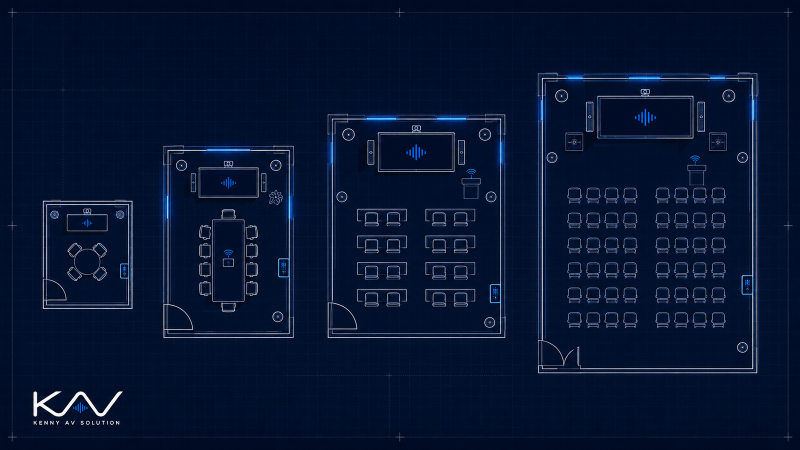
Huddle Rooms and Small Meeting Spaces
Huddle rooms are the high-volume, low-complexity end of the corporate spectrum: two to six people, a single display, an all-in-one video bar, a wireless presentation receiver, and not much else. The temptation is to skip the drawings entirely. Don’t. Even a huddle room needs a documented standard, because the client is going to build forty of them and they all have to be identical.
The drawings for a huddle room are simple but specific: display size and center height (typically 48 to 60 inches AFF), the wall plate or floor-box location with its exact connectors, the video bar mounting position relative to the display, the single network drop, and a one-line signal flow that applies to every huddle room in the building. Document it once, reference it everywhere.
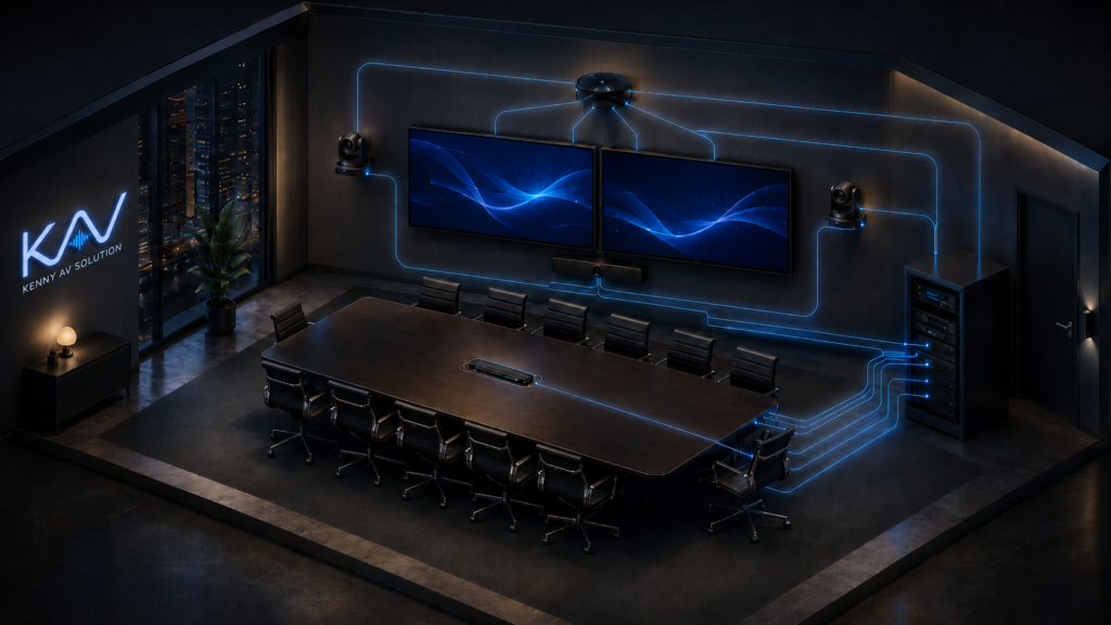
Boardrooms — Where the Detail Lives
The boardroom is the showcase space and the one most likely to generate field RFIs, so it gets the most detailed drawings. A typical corporate boardroom has dual displays or a single large display, a video conferencing codec, one or more PTZ cameras, a ceiling microphone array, ceiling speakers, a table with integrated connectivity and a cable cubby, and a touch panel for control.
Your signal flow diagram for a boardroom needs to show the codec at the center, every source and destination, the audio DSP, and how the room joins a unified communications platform like Teams or Zoom. The reflected ceiling plan has to place the microphone array precisely — coordinated around HVAC diffusers, sprinklers, and lighting — because mic placement makes or breaks the conferencing experience. And the table needs a detail sheet showing the floor box, the cable cubby, and exactly which cables terminate where.
Training Rooms and Divisible Spaces
Training rooms add scale and a wrinkle: they are often divisible. A 60-seat training room that splits into two 30-seat rooms with an operable partition needs documentation for combined and divided modes — separate audio zones, display routing logic, and a control system that reconfigures when the wall moves. The drawings have to show the partition position sensor, the audio zoning, and the signal routing for each mode.
Training rooms also introduce voice lift (reinforcing the presenter’s voice in the room, not just for remote participants), program audio, lectern and wireless microphones, and usually a proper AV rack with a DSP. The cable schedule and rack elevation get real here. Document the DSP configuration intent in the control narrative so the commissioning engineer knows what the room is supposed to do.
All-Hands and Town Hall Spaces
At the top of the corporate spectrum sits the all-hands space — a large multipurpose room, sometimes a repurposed cafeteria or atrium, that hosts company-wide meetings for hundreds in the room and thousands streaming. This is where corporate AV starts to resemble a small broadcast facility: an LED wall or large-format projection, a line-array or distributed reinforcement system, multiple cameras feeding a switcher, a streaming and recording encoder, redundant DSP, and a control system an AV operator actually drives.
The documentation requirements scale accordingly. The signal flow diagram can run several pages. The structural coordination is real — an LED wall and a line array both need engineered support, and those load numbers belong on the drawings for the structural engineer and the GC. Rigging points, power distribution, heat load, and acoustic treatment all get coordinated. Treat the all-hands space as the most demanding documentation deliverable on the project, because it is.
Mounting Heights and Cross-Trade Coordination
Every corporate AV set should include a mounting heights schedule and explicit coordination notes. The heights schedule prevents the bulk of your field RFIs — display center at 60 inches AFF, table touch panels and cable cubbies at table height, cameras at seated eye line, control surfaces within ADA reach ranges. The coordination notes protect you across trades:
- Electrical: dedicated circuits and floor boxes for racks and tables, isolated grounds where the audio design requires them. Every AV device that needs power should match a callout on the EC drawings.
- Low-voltage / IT: network drops per room with count, location, and VLAN, plus service loops where cable runs to a table or codec.
- Mechanical: rack and display heat loads handed to the HVAC engineer, and a ceiling kept clear of diffusers around microphone arrays.
- Structural: backing and load for displays, LED walls, and line arrays — get the numbers on the drawing.
- Lighting and IT systems: lighting scene integration with the AV control system, and the room-scheduling and calendar feed corporate IT will connect to.
Put a coordination note on every sheet that has a cross-trade dependency — “Coordinate with E-201 for power, T-101 for network drops.” It reads as professional and it covers you when something slips in the field.
Standardize, Then Reference
The single biggest efficiency in corporate AV documentation is the room-type template. Define a “Boardroom Type A,” draw it once in full, and then let the room schedule assign that type to every matching space in the building. New office, same standard, same drawings. It keeps a multi-site rollout consistent and it makes the eventual as-built drawings dramatically easier to produce.
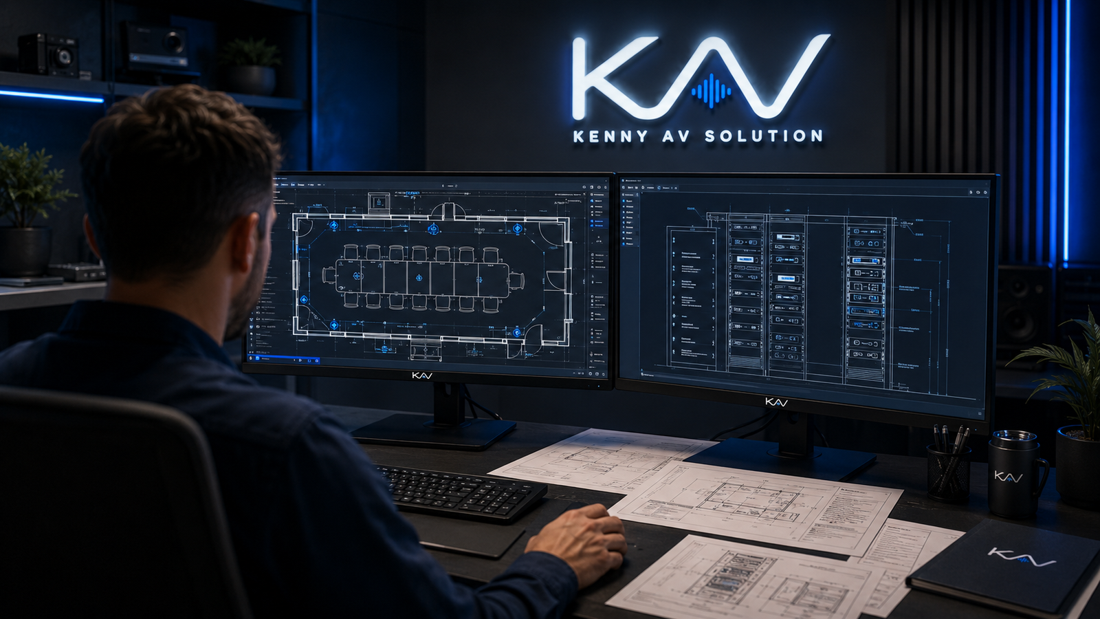
Need Corporate AV Documentation Drafted?
Kenny AV Solution drafts corporate AV design documentation for AV integrators serving commercial workplace clients — huddle rooms, boardrooms, training rooms, divisible spaces, and all-hands town halls. We work in AutoCAD, Revit, Visio, D-Tools, and XTEN-AV, and we build room-type templates and standards packages that scale cleanly across multi-site rollouts.
Whether you have a single boardroom refresh or a campus-wide workplace program on your desk, contact Kenny AV Solution for a quote and turnaround estimate. Our drafters deliver documentation your install crews and your client’s IT team will actually use.
Related reading: Conference Room AV Wiring Diagrams, AV Floor Plans vs Reflected Ceiling Plans, and AV Design for Education.