Most AV projects don’t fail in the field. They fail on the drawings. By the time a low-voltage installer is staring at a ceiling grid wondering why the projector mount is on the wrong column line, the actual mistake was made weeks earlier — somewhere in the construction documents nobody bothered to QA.
AV construction drawings sit at the intersection of architecture, electrical, IT, and AV trades, and that intersection is where small documentation errors turn into expensive jobsite problems. Drywall gets opened. Conduits get re-pulled. Change orders get signed. Schedules slip. Most of it is preventable.
This guide walks through the five mistakes we see most often in AV construction drawings — the ones that consistently cause the worst downstream pain — and what to do instead.
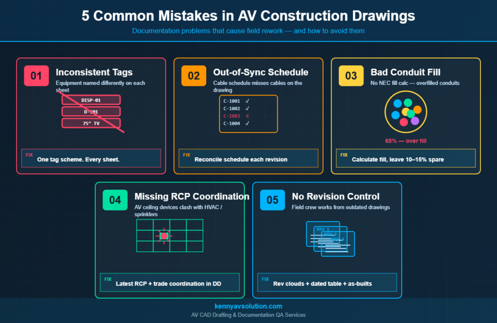
Mistake 1: Inconsistent Equipment Tags Across Sheets
This is the single most common AV documentation problem and the easiest to spot. The boardroom display is tagged DISP-01 on the floor plan, D-101 on the rack elevation, and just “75” Display” on the equipment schedule. By the time the integrator gets to commissioning, nobody is sure whether those three references describe the same device or three different ones.
Inconsistent tags break almost every downstream process: bid takeoffs, procurement, programming, commissioning, and post-install service. The tech who shows up two years later to fix a no-audio call is going to look at the drawing, look at the rack, and start guessing.
How to Avoid It
- Define an equipment tag scheme at project kickoff and put it on the cover sheet
- Use the same tag on every drawing the device appears on — floor plan, RCP, rack elevation, signal flow, cable schedule
- Cross-reference the tag in the equipment schedule with manufacturer model numbers
- Run a tag QA pass before issuing for construction — every tag should appear on at least three sheets, and every reference should resolve to one device
Following the AVIXA AV drawing symbols standard for equipment naming makes this easier — there’s a published convention, so use it.
Mistake 2: A Cable Schedule That Doesn’t Match the Drawings
The AV cable schedule is supposed to list every individual cable in the system — source, destination, type, length, conduit ID. When it gets out of sync with the drawings, two problems happen: cables get ordered in the wrong quantities, and pulls happen through conduits that were never sized for them.
The disconnect usually shows up in revision cycles. Somebody adds a microphone in the boardroom on the floor plan, draws the cable on the signal flow, and forgets to add a row to the cable schedule. The cable doesn’t get ordered. The mic doesn’t work on opening day.
How to Avoid It
- Treat the cable schedule as the single source of truth for cable counts
- Use a CAD tool that links the schedule to the drawing — or run a manual reconciliation pass each revision
- Number every cable with a unique ID (e.g.,
C-1001) that appears on the drawing AND in the schedule - Reconcile cable counts against conduit fill before issuing — every cable should have a documented pathway
Mistake 3: Conduit Fill Not Calculated (Or Calculated Wrong)
NEC Chapter 9 spells out exactly how full a conduit can be: 53% for one cable, 31% for two, and 40% for three or more. This isn’t a suggestion. AHJs will fail an install for over-filled conduit, and pulling a 41% conduit through a 100-foot run with two 90-degree bends is going to damage cable jackets even if the inspector lets it slide.
Despite this, conduit fill calculations are routinely missing from AV construction drawings. The conduit is sized at design time based on a guess, the EC installs it, and then the AV team shows up with more cables than will fit. Now somebody has to either pull a second conduit (concrete, drywall, ceiling) or de-scope cables.
How to Avoid It
- Calculate fill percentage for every conduit on the conduit schedule
- Use NEC Chapter 9 cable diameter tables — not estimates
- Leave 10–15% spare capacity for future cables (it costs nothing on paper, a fortune in the field)
- Show the fill calculation on the drawing so reviewers can verify
For a deeper dive into how this fits with riser planning, see our guide to AV conduit and riser diagrams.
Mistake 4: Missing or Outdated Reflected Ceiling Plan
The reflected ceiling plan (RCP) is where ceiling-mounted AV devices live: projectors, ceiling speakers, microphones, displays on dropped supports, occupancy sensors, smoke detectors that the GC’s mechanical engineer also wants to put right where the projector is going. If the AV designer doesn’t put devices on the RCP — or uses an outdated RCP from the architect — collisions happen.
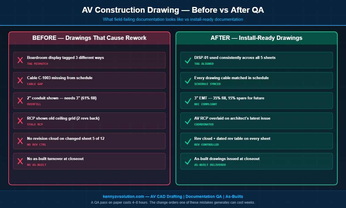
Common RCP failures: the projector mount lands on a sprinkler head, the speaker grid clashes with HVAC diffusers, ceiling tile centers are wrong because the RCP is two revisions old. None of these are caught until the installer is on a lift trying to find a stud.
How to Avoid It
- Always pull the latest RCP from the architect before starting AV layout — verify the revision date
- Coordinate with the mechanical and fire protection trades during DD, not at install
- Use a layered AV RCP that overlays AV devices on the architect’s RCP, not a redrawn one
- Mark known clearance requirements on the drawing (projector throw distance, speaker dispersion patterns)
For a full breakdown of how RCPs and floor plans work together, see AV floor plans vs reflected ceiling plans.
Mistake 5: No Revision Control or As-Built Handover
AV construction drawings change. They change a lot. Between schematic design and project closeout, a typical set goes through 5–10 revisions. Without proper revision control — clear revision clouds, dated revision tables, version numbers — the field crew has no way to know which sheet is current. They pull from the latest PDF on the GC’s project portal and hope it’s right.
The endgame mistake is even worse: the project finishes, the integrator never produces an as-built drawing, and a year later when something breaks, the service tech is reverse-engineering the system from a stack of PDFs that were never updated to reflect what actually got installed.
How to Avoid It
- Use revision clouds and a dated revision table on every sheet — every revision, every time
- Issue revisions as a complete set with a transmittal, not as one-off sheets
- Maintain a redline copy on the jobsite during construction
- Produce AV as-built drawings at project closeout — this is non-negotiable for any project where you want to be invited back for service work
Why These Mistakes Keep Happening
None of these mistakes are caused by lack of skill. They happen because AV documentation is often the last deliverable and the first thing to get squeezed when budgets tighten. Drafting hours get cut. QA passes get skipped. Revisions get issued without a transmittal because somebody is in a hurry.
The fix isn’t more talent — it’s more discipline. A documentation package that catches all five of these problems before the drawings go out for construction takes maybe 4–8 extra hours over the life of a project. The change orders and rework one of these mistakes can generate easily run into the tens of thousands.
Where Construction Drawing QA Fits In
The most reliable way to avoid all five mistakes is a structured QA pass before every issuance. Walk through the drawing set with a checklist:
- Tag check: Pick five random equipment tags and verify they appear consistently on the floor plan, RCP, rack elevation, and equipment schedule
- Schedule check: Pick five random cables and verify they appear in the schedule with the correct conduit ID, source, and destination
- Conduit check: Verify fill calculations on every conduit, with at least 10% spare
- RCP check: Confirm the RCP revision matches the architect’s latest issuance
- Revision check: Confirm the revision table on the cover sheet matches the rev number on every individual sheet
This kind of QA is the difference between a drawing set that gets installed cleanly and one that generates change orders. It’s also one of the things AV CAD specialists do as a standard part of their workflow — see our breakdown of the complete AV design documentation package for what a full set should look like.
Let Kenny AV Solution QA Your AV Construction Drawings
If your team is producing AV construction drawings in-house and you’re seeing any of these five mistakes show up on jobsites, the cheapest fix is a second set of eyes before drawings go out for construction. Kenny AV Solution offers AV documentation drafting and QA services for integrators across North America — we produce install-ready drawing sets and can also review your existing documentation against AVIXA and NEC requirements.
Every drawing package we deliver is tag-consistent, schedule-synced, fill-calculated, RCP-coordinated, and revision-controlled — because we’ve fixed every one of these mistakes in the field, and we’d rather catch them on paper.
Need help cleaning up your AV construction documentation? Contact Kenny AV Solution today and let’s talk about your project scope.