
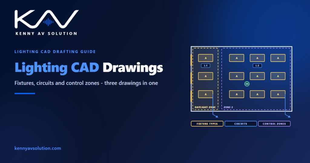
Lighting CAD drawings look like one drawing — a reflected ceiling plan full of fixtures — but they carry three different kinds of information at once. Where each fixture is. How it is powered: which circuit, from which panel. And how it is controlled: which switch, sensor or scene turns it on, off or down. The three are related, but they are not the same, and most lighting drawing problems come from treating them as if they were.
Lighting design — illuminance levels, fixture selection, emergency lighting and energy-code compliance — is the responsibility of the lighting designer and electrical engineer under the codes that apply, such as the NEC and an energy code like ASHRAE 90.1 or the IECC in the United States, or Part L and BS 5266 in the UK. The figures below are illustrative; the engineer of record governs.
The fixture schedule comes first
Every fixture on the plan carries a type tag — A, B, C or similar — and the tag points to the fixture schedule, which is where the real information lives. A useful schedule gives, for each type:
- Manufacturer, model and description.
- Light source: lumen output, colour temperature and colour rendering.
- Input power in watts, and voltage.
- Driver and dimming method — for example 0-10 V, DALI or phase dimming.
- Mounting: recessed, surface, pendant with drop length, or wall-mounted with height.
- Finish, accessories and any emergency battery.
The schedule is what the contractor prices and orders from, and what the circuiting depends on: the wattage per fixture is the input to every circuit load. Keep the types few and consistent across the project, the same way as plate types or door types.
Layout: drawn on the ceiling, coordinated with everything else on it
Fixture layouts belong on the reflected ceiling plan, set out from the ceiling grid or from fixed dimensions to walls. They share that ceiling with sprinklers, diffusers, smoke detectors, loudspeakers, cameras and projectors, so the layout has to be coordinated with the other trades before it is issued; see trade coordination. Light falling on a projection screen is a classic clash, and one the projector placement drawings should flag.
The layout itself normally follows the lighting designer’s photometric calculations. The drafting job is to place the fixtures exactly as designed, dimension them, and keep the type tags correct as the design changes.
Circuiting: load every circuit, and leave headroom
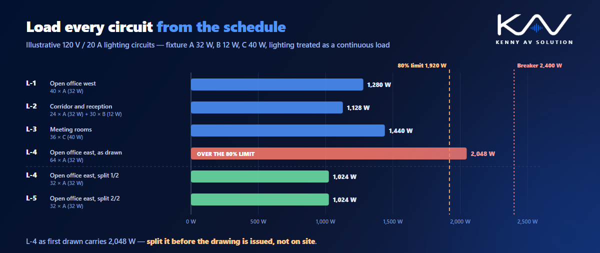
Circuiting assigns each fixture to a branch circuit in a panel. On the drawing, each fixture is tagged with its circuit number, and a home-run arrow shows where each circuit leaves the area for its panel.
Lighting usually runs for hours at a time, so it is treated as a continuous load. Under the NEC, a continuous load should not exceed 80% of the breaker rating. On a 120 V, 20 A circuit that is 1,920 W; on a 277 V, 20 A circuit it is 4,432 W, which is one reason larger commercial buildings light at 277 V. Add up the wattage from the fixture schedule for every circuit and show it on the panel schedule.
Wattage is not the only limit. LED drivers draw a short inrush current when switched on, and manufacturers often state a maximum number of drivers per breaker or relay. Check it for circuits with many fixtures, even when the wattage is well inside the limit.
Control zones are not circuits
A circuit is about power. A control zone is about how the space is used. One circuit can feed fixtures in several control zones, and one zone can include fixtures from several circuits — so draw them separately.
Show control zones as their own outlines or tags on the plan, with the switch, sensor or keypad that controls each. Energy codes typically require automatic controls such as occupancy sensors, and separate control of fixtures in daylight zones near windows, so those zones need to be visible on the drawings. Where the system uses networked or addressable controls such as DALI, add a control riser showing the controllers, the bus or network, and the addressing.
In meeting rooms, lecture halls and worship spaces, lighting is often recalled as scenes from the AV control system — “presentation” dims the front zone and keeps the seating lit. That interface belongs on both the lighting control riser and the AV signal flow, with the responsibility for each side stated in the responsibility matrix.
Emergency lighting
Some fixtures stay on, or come on, when normal power fails, to light the escape routes. Mark every emergency fixture clearly, show its source — an integral battery, a central battery or a generator — and show any transfer device that switches a normal fixture onto emergency power. Exit signs belong on the same drawings. Emergency lighting is life-safety work, reviewed alongside the fire alarm drawings, so keep the two sets consistent.
What a lighting drawing set contains
- A fixture schedule with type, model, source, wattage, voltage, dimming and mounting.
- Lighting layouts on the reflected ceiling plans, dimensioned and coordinated.
- Circuiting with circuit numbers, home runs and panel schedules showing the load on every circuit.
- Control zones, switches, sensors and keypads, with daylight zones shown.
- A control riser for networked or addressable systems.
- Emergency lighting and exit signs with their power source.
- Interfaces with AV and building management, shown on both sides.
Keep tags, symbols and text consistent with the rest of the set using your drawing standards.
Frequently asked questions
What should a lighting fixture schedule include? For each fixture type: the type tag, manufacturer and model, light source details such as lumen output and colour temperature, input wattage and voltage, driver and dimming method, mounting, finish and any emergency battery.
How many lights can go on one circuit? It depends on the wattage and the circuit. Lighting is a continuous load, so under the NEC it should not exceed 80% of the breaker rating — 1,920 W on a 120 V, 20 A circuit or 4,432 W at 277 V. LED driver inrush current can also limit the number of fixtures per breaker, so check the manufacturer’s data.
What is the difference between a lighting circuit and a control zone? A circuit is how fixtures are powered from the panel; a control zone is how they are switched or dimmed. One circuit can feed several control zones and one zone can include several circuits, so they should be shown separately on the drawings.
What are daylight zones on a lighting plan? Areas near windows or skylights where daylight is enough to reduce the electric lighting. Energy codes typically require fixtures in those areas to be controlled separately, so the zones should be marked on the drawings.
How is emergency lighting shown on lighting drawings? Each emergency fixture is marked clearly with its power source — an integral battery, a central battery or a generator — along with any transfer devices and exit signs, and the drawings are kept consistent with the fire alarm and life-safety documents.
Need lighting CAD drawings drafted?
Kenny AV Solution drafts lighting documentation alongside AV and low-voltage systems for electrical contractors, lighting designers and integrators worldwide — fixture layouts and schedules, circuiting and panel schedules, control zones and risers, and emergency lighting plans, drawn to your standards and your title block. Send us the reflected ceiling plans and the lighting design. See our drafting services, grab the free AV CAD Drafting Standards Checklist, or schedule a quick call — we come back with a quote and timeline within one business day.