
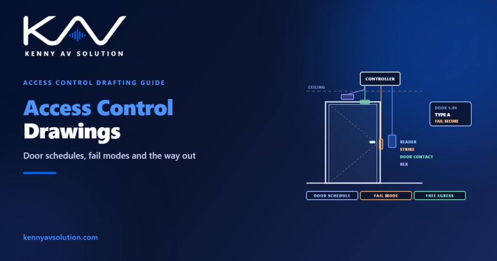
Access control drawings look simple: a reader beside a door, a lock in the frame, a line back to a controller. But an access-controlled door is where four or five trades meet in one opening — the door and hardware supplier, the electrician, the access control contractor, the fire alarm contractor and the architect — and each of them assumes something about the others. The drawings are where those assumptions either get written down or turn into a door that does not work on handover day.
How locked doors must release for people to leave is set by building and fire codes and the authority having jurisdiction. The examples below are illustrative; confirm egress, fire door and hardware requirements on each project with the architect, the hardware supplier and the authority.
One door, several trades
Take a single card-access door. The door hardware supplier provides the lock or strike, the hinges and the closer as part of a hardware set. The electrician provides power and backboxes. The access control contractor provides the reader, the controller and the cabling. The fire alarm contractor may need to release the door. The architect decides whether it is on an escape route and whether it is fire-rated.
None of them can finish their part without information from the others. The electrified lock has to suit the access control system’s voltage; the frame has to be prepared for it; the cable has to reach the door leaf; the release has to be agreed with the fire strategy. Write down who provides what for every device, as in the responsibility matrix, and coordinate it the same way as any other trade interface.
The door schedule is the contract
The most useful access control document is not the floor plan. It is the door schedule.
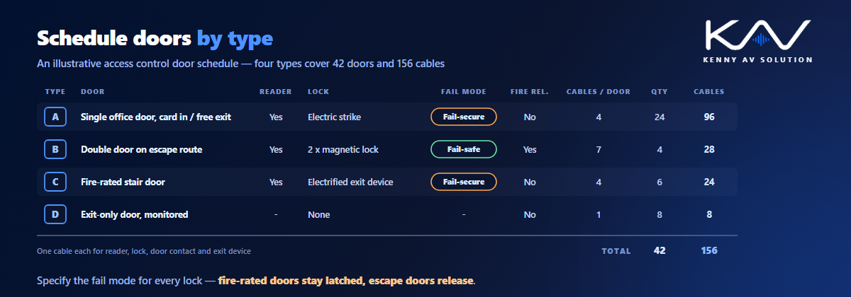
List every controlled door by the same door number as the architect’s door schedule, so that both schedules describe the same opening. For each door give its type, the devices on it, the lock and its fail mode, whether it releases on fire alarm, the controller it connects to and the cable IDs. Group doors into types — a single office door, a double door on an escape route, a fire-rated stair door — with one detail per type, as with plate types. The type tells the installer what is on the door; the schedule tells procurement how many of each.
Check the access control schedule against the architect’s hardware sets. A door scheduled for an electric strike in one document and a mechanical lockset in the other is the most common conflict, and it is far cheaper to find on paper.
Fail-safe, fail-secure and the way out
Every electrified lock has a fail mode: what it does when it loses power.
- Fail-safe — the door unlocks when power is removed. Magnetic locks work this way by nature.
- Fail-secure — the door stays locked from the outside when power is removed, while still allowing people to leave from the inside mechanically.
Electric strikes and electrified locksets are available either way, so the fail mode has to be specified, not assumed. The choice is driven by security on one side and safe egress on the other. Codes generally require that people can leave without special knowledge or effort, and they have specific provisions for electrically locked doors on escape routes — often involving a request-to-exit device, a manual release and release on fire alarm. Fire-rated doors bring a further constraint: they have to stay latched in a fire, which limits which electrified hardware can be used. Show the fail mode and the release method on the schedule for every door, and agree them with the architect and the authority.
Where the fire alarm releases doors, that interface belongs on the fire alarm riser as well; see fire alarm drawings.
Getting power into the door
A strike sits in the frame and is easy to reach. An electrified lockset or exit device sits in the door leaf, which moves. Power has to cross the hinge.
That is done with an electrified hinge or power transfer device and a raceway through the leaf, all of which must be ordered with the door and frame — they cannot be added on site without damaging a finished, sometimes fire-rated, door. Show it on a typical door elevation and section for each door type: reader position and height, lock, door contact, request-to-exit device, power transfer and the cable route into the frame. Mounting heights and reach for readers and buttons follow the same rules as other user controls; see wall elevations and mounting details.
Readers, controllers and the riser
Each controlled door connects back to a door controller, usually on the secure side — above the ceiling inside the protected area, or in a communications room — never on the public side where it could be tampered with. Show each controller, the doors it serves, its power supply with battery backup, and its network connection. The network side follows the same documentation as AV over IP network diagrams and the security expectations in AV network security documentation.
A typical door has several cables — reader, lock power, door contact, request-to-exit — each with its own ID on the cable schedule. Multiply by the number of doors and the cable count grows quickly, which is another reason to schedule by door type.
Door entry and intercom
Door entry systems — audio or video intercom stations at entrances, answered at reception or by residents — are drawn alongside access control because they release the same doors. Show the outdoor station with its mounting height, the answering stations, the door each one releases and how the release is wired into the lock. Where cameras cover the entrance, coordinate with the CCTV coverage drawings so that faces at the door are actually captured.
What an access control drawing set contains
- Floor plans with every controlled door, reader, controller and door entry station.
- A door schedule using the architect’s door numbers, with type, devices, lock, fail mode and fire release for each door.
- Typical door details for each type: elevation and section with devices, power transfer and cable route.
- A riser or block diagram of controllers, power supplies and the network.
- Wiring schematics for each door type.
- A cable schedule with an ID for every run.
- A responsibility split between hardware, electrical, access control and fire alarm.
Frequently asked questions
What should an access control door schedule include? Every controlled door, identified by the architect’s door number, with its door type, reader, lock type and fail mode, door contact, request-to-exit device, whether it releases on fire alarm, the controller it connects to and its cable IDs.
What is the difference between fail-safe and fail-secure locks? A fail-safe lock unlocks when it loses power; a fail-secure lock stays locked from the outside, while still allowing people to leave from the inside mechanically. Magnetic locks are fail-safe by nature; electric strikes and electrified locksets are available either way, so the fail mode must be specified.
How does power get to a lock in the door leaf? Through an electrified hinge or a power transfer device and a raceway in the door, which have to be ordered with the door and frame. They should be shown on the typical door details for each door type.
Where should access control controllers be located? On the secure side of the doors they control, such as above the ceiling within the protected area or in a communications room, with a backed-up power supply and a network connection. They should not be reachable from the public side.
Why do access control and fire alarm drawings need to agree? Because doors on escape routes often have to release when the fire alarm operates. That interface should be shown on both the access control and fire alarm drawings, with the responsibility for each side stated.
Need access control drawings drafted?
Kenny AV Solution drafts access control and door entry documentation alongside AV, CCTV and fire alarm systems for contractors worldwide — door schedules matched to the architect’s numbering, typical door details, controller and network risers, wiring schematics and cable schedules, drawn to your standards and your title block. Send us the floor plans, door schedule and device list. See our drafting services, grab the free AV CAD Drafting Standards Checklist, or schedule a quick call — we come back with a quote and timeline within one business day.