
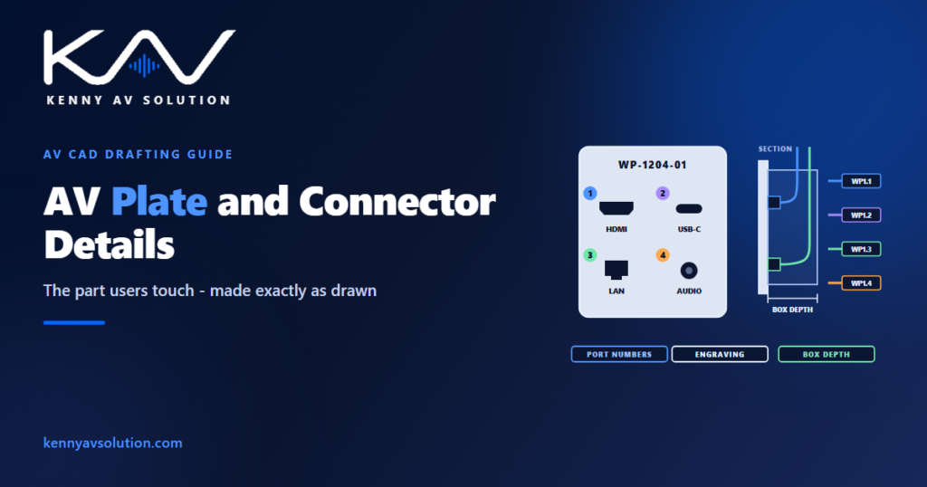
AV wall plate details describe the only part of an AV system most people ever touch. Users never see the rack, the processor or the cable schedule; they see a plate in the wall, the floor or the table, and they plug a laptop into it. That plate is also, quite often, a manufactured part — cut, engraved and finished to order from your drawing. Whatever the detail says is what arrives, and whatever it leaves out is decided by somebody else.
A plate detail is a manufacturing drawing
Standard plates come out of a catalogue. Custom plates are made to order: the fabricator cuts the openings, fits the connectors and engraves the labels exactly as drawn. The detail is not an illustration of intent; it is the purchase document.
So draw it like one. Each plate type needs its face layout to scale, with every connector’s position, the manufacturer and model of each connector or insert, its orientation, the engraving text with its size and position, the plate material, colour and finish, and the mounting format — gang size for a North American box, or the regional module size elsewhere, which is not the same thing.
Custom plates also carry a lead time and usually an approval step. Issue the plate details early, with the rest of the shop drawings, so the plates are not the last thing holding up a room that is otherwise finished.
Every connector has a direction
A connector on a plate is the end of a signal path, and the detail should make clear which way that path runs.
Show whether each connector is an input to the system or an output from it, and its gender. An HDMI connector a laptop plugs into and an HDMI connector feeding a confidence monitor look identical on the plate and do opposite jobs in the system. The signal flow diagram should show the plate as a device, with each port, so the two documents agree.
Distinguish three kinds of plate clearly:
- Terminated — the cable is terminated on the back of a connector.
- Pass-through — a brush or grommet opening that cables pass through to equipment behind.
- Active — the plate contains electronics, such as an extender transmitter or a network-based encoder.
Active plates bring their own requirements: power (often over the network cable, which the switch then has to supply), more depth behind the plate, a little heat, and a partner device elsewhere in the system. Note the pairing and the power source on the detail, and make sure the switch port is on the network documentation described in AV over IP network diagrams.
Number the ports, not just the plate
Giving each plate an ID is common. Numbering each port on it is what makes the documentation traceable.
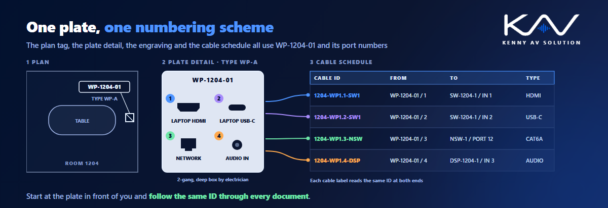
Tag every plate on the plan with a unique ID — for example WP-1204-01 for the first wall plate in room 1204 — and number every port on its detail. The cable schedule then references the plate and port at each cable end, the engraving or label on the plate matches, and the label on the cable matches both. Someone tracing a fault can start at the plate in front of them and follow the same identifier through every document. For the cable labels themselves, AVIXA’s ANSI/AVIXA F501.01 cable labelling standard is the reference to align with.
Write the scheme down once, in your AV drawing standards, rather than inventing it per project. Mixing “Plate A” on the plan, “FB-3” in the schedule and “Table input” on the engraving is how a cable gets terminated on the wrong port.
Depth, bend radius and the box behind the plate
The face of the plate is only half the detail. The other half is what fits behind it.
Connector bodies, cable bend radius and any electronics together set the minimum box depth. A thick, stiff cable plugged straight into the back of a connector needs room to curve before it reaches the conduit; force it into a shallow box and it strains the termination or kinks. State the box size and depth on the detail, so the electrician installs the right box at rough-in rather than the standard one, and coordinate who provides it through AV trade coordination.
Floor boxes and table boxes deserve extra care, because their inserts are specific to the manufacturer. Confirm that each insert actually fits the box or the table module specified, that the box depth suits a raised floor or a slab, and that the furniture cutout matches the manufacturer’s template. A table box is a joint detail with the millwork drawings, as described in corporate AV design documentation.
Draw types, not one-offs
A building may contain hundreds of plates and only a handful of different ones. Treat them that way.
Define each distinct plate as a type — WP-A, FB-B, TB-C — with one detail per type and a plate schedule listing every plate, its type, location, mounting height and any variation. The plan symbol shows the tag, the schedule says which type it is, and the detail shows what that type contains. The schedule also gives procurement a count per type without anyone having to count symbols on a plan.
Keep variations honest. If two plates differ only in engraving, they can share a type with the engraving listed per plate in the schedule. If they differ in connectors, they are different types.
Where people actually plug in
A plate that is correct on paper can still be wrong in use.
Place user-facing connectors where people can see and reach them: on the table rather than under it, within reach on the wall, and not in a floor box that ends up under a chair. Wall-mounted plates that users operate fall under the same reach-range rules as other controls; heights and accessibility are covered in AV wall elevations and mounting details. Make engraving large and plain enough to read at arm’s length, and name the signal rather than the cable: “Laptop HDMI” is more use to a visitor than “HDMI IN 1”.
What a complete plate and connector detail sheet contains
- One detail per plate type, with the face drawn to scale.
- Connector make and model, orientation, gender and signal direction for every port.
- Port numbers matching the cable schedule.
- Engraving text, size, position, and the plate material and finish.
- Plate type — terminated, pass-through or active — with power and pairing for active plates.
- Box or insert: gang or module size, depth, and who provides it.
- A plate schedule with every plate’s ID, type, location and height.
- Furniture cutouts for table boxes, coordinated with the millwork.
Because every port is numbered, the same sheets become the checklist when the system is tested; see AV commissioning and performance verification.
Frequently asked questions
What is an AV plate detail? A drawing of a wall plate, floor box insert or table box showing its face to scale, each connector’s make, model and position, the port numbers, the engraving, the finish and the box it mounts in. For custom plates it is the document the fabricator builds from.
What should be engraved on an AV wall plate? A plate ID that matches the plan tag, and a plain description of each connector’s purpose, such as “Laptop HDMI” or “Network”. Port numbers should match the cable schedule so the plate, the drawings and the cable labels all use the same identifiers.
What is the difference between a terminated, pass-through and active wall plate? A terminated plate has cables terminated on the back of its connectors. A pass-through plate has an opening that cables pass through to equipment behind it. An active plate contains electronics, such as an extender transmitter, and needs power, extra depth and a paired device elsewhere in the system.
How deep should the box behind an AV wall plate be? Deep enough for the connector bodies, the cable bend radius and any electronics in the plate. That depends on the connectors and cables used, so it should be stated on the plate detail, so the electrician installs the right box at rough-in.
Why use plate types and a plate schedule? Because most buildings have many plates but few distinct designs. One detail per type, plus a schedule listing every plate’s ID, type, location and height, keeps the drawings short, makes variations explicit and gives procurement a count per type.
Need AV plate and connector details drafted?
Kenny AV Solution produces AV drawing sets in AutoCAD for integrators and consultants worldwide — plate and connector details, plate schedules, floor plans and RCPs, wall elevations, signal flow diagrams, rack elevations and cable schedules, all on one numbering scheme and drawn to your standards and your title block. Send us your design and equipment list, and we will produce details your fabricator, electrician and installers can all work from. See our AV CAD drafting services, grab the free AV CAD Drafting Standards Checklist, or schedule a quick call — we come back with a quote and timeline within one business day.