
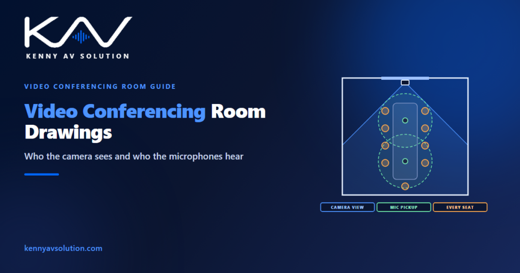
Video conferencing room drawings are usually judged by the people in the room, but the room is really built for the people who are not in it. The far end sees only what the camera frames and hears only what the microphones pick up. A drawing that shows a camera symbol above the display and a few microphones on the table says nothing about either. A good one shows who the camera can see and who the microphones can hear, seat by seat, before anything is installed.
Camera angles of view, microphone pickup patterns and coverage areas vary by product, and the manufacturer’s data governs. The figures below are illustrative geometry, not product recommendations.
Start with the seats, not the equipment
Every decision in a video conferencing room follows from the seating plan: where people sit, how many, and which of them must be seen and heard. Draw the table and every chair to scale on the floor plan, and add the other positions that matter — a presenter at the front, a whiteboard, seats along the wall that are used when the room is full.
Get the furniture layout confirmed early. The table shape and the distance from the front wall to the first seats decide whether one camera can do the job, and that is much cheaper to change on the drawing than after the furniture has been bought. In an existing room, confirm the dimensions with a site survey.
Camera position: at the display, near eye level
The camera normally sits at the front of the room, centred on the display, so participants look towards it while they watch the far end. The closer it is to the image of the far-end faces, the more natural the eye contact. Mount it close to seated eye height — just above or just below the display — rather than high on the wall looking down.
Show the camera on the wall elevation with its height and its relation to the display, and coordinate the display size with the viewing distances using display sizing. Check what the camera will see behind the participants as well: a window behind the seats backlights every face.
Draw the field of view — and the trade-off
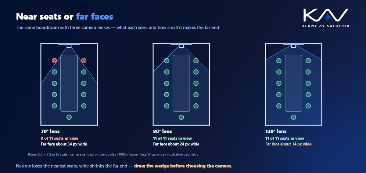
Draw the camera’s horizontal field of view on the plan as a wedge from the lens, using the angle of view from the data sheet. Every seat that must be seen should fall inside it. The seats most likely to fall outside are not at the far end but the nearest ones: the seats closest to the front wall sit at the widest angle from the camera.
A wider lens solves that, but it creates the opposite problem. The wider the angle, the wider the area the camera fits into the same number of pixels, so the people at the far end of the table become smaller in the picture. In the illustrative boardroom below, a 70° lens loses the two nearest seats but keeps the far face about 34 pixels wide in a 1080p frame; a 120° lens sees every seat but shrinks the same face to about 14 pixels.
Ways to resolve it
When no single lens angle works, the drawing should show the fix that was chosen:
- Move the first seats back from the front wall, or use a table shape that keeps the nearest seats inside the view.
- Use a camera with a wide lens and a high-resolution sensor, so it can crop in on the people who are speaking while still seeing everyone; check how it frames and how it is controlled.
- Add a second camera, for example one for the table and one for a presenter, and show what each one covers.
- Move the camera further from the first seats, where the room allows it.
Microphones: draw the pickup, not the symbol
The far end hears what the microphones pick up, so draw their coverage the same way as the camera’s. Whether the system uses table microphones, ceiling microphones or beamforming arrays, take the pickup pattern or coverage area from the manufacturer’s data and draw it to scale. Every talker position should fall inside it.
Ceiling microphones belong on the reflected ceiling plan as well, coordinated with lights, diffusers and sprinklers. Keep them away from air outlets and from the room’s loudspeakers, and show the cabling and power in the conference room wiring diagrams. Table microphones need floor or table boxes in the right places, detailed with the connector plates.
Loudspeakers, echo and the room itself
The far end also hears the room. Loudspeakers that play the far-end audio are picked up again by the microphones, and the system uses acoustic echo cancellation to remove it. That processing works far better in a room that is not too reverberant, with loudspeakers placed sensibly in relation to the microphones. Show the loudspeakers and their coverage as in loudspeaker coverage drawings, and show the microphones, processor and loudspeakers on the signal flow diagram.
Lighting matters to the camera as much as to the people in the room. Faces need even light from the front, without hard shadows from downlights directly overhead; coordinate the fixtures and control zones with the lighting drawings.
What the drawings should show
- A furniture plan with every seat and other position that must be seen or heard.
- Camera field of view drawn to scale from the lens, with the angle of view stated, and any seat outside it identified.
- Microphone pickup zones to scale, covering every talker position.
- A wall elevation with the display, the camera height and its relation to the screen.
- A reflected ceiling plan with ceiling microphones, loudspeakers and lighting coordinated.
- Signal flow and wiring for the codec, cameras, microphones, processor and loudspeakers.
- A verification step at commissioning: check the picture from every seat and test the audio from every talker position.
The same checks apply from a huddle room to a boardroom; the larger the table, the more the geometry decides the design.
Frequently asked questions
Where should the camera go in a video conferencing room? Usually at the front of the room, centred on the display and close to seated eye height, just above or below the screen. That keeps participants looking towards the camera while they watch the far end, which gives more natural eye contact.
What camera field of view does a meeting room need? One wide enough to include every seat that must be seen, especially the seats nearest the front wall, which sit at the widest angle. A wider lens makes far-end faces smaller in the picture, so the angle should be checked on the plan against both the nearest and the farthest seats.
Why do seats near the camera fall out of the picture? Because the seats closest to the front wall are at the widest angle from the camera. A seat beside the table and close to the camera can sit outside a narrow field of view even though the far end of the table is well inside it.
How should microphones be shown on AV drawings? With their pickup patterns or coverage areas drawn to scale from the manufacturer’s data, so it is clear that every talker position is covered. Ceiling microphones should also be coordinated on the reflected ceiling plan with lights, air outlets and loudspeakers.
What should video conferencing room drawings include? A furniture plan, the camera field of view and microphone pickup drawn to scale, a wall elevation with the camera and display, a coordinated reflected ceiling plan, the signal flow and wiring, and a commissioning check of picture and audio from every seat.
Need video conferencing room drawings?
Kenny AV Solution drafts AV documentation for integrators, consultants and design-build teams worldwide — meeting room plans with camera and microphone coverage, wall elevations, reflected ceiling plans, signal flow diagrams and wiring, drawn to your standards and your title block. Send us the room plans, the furniture layout and the equipment list. See our drafting services, grab the free AV CAD Drafting Standards Checklist, or schedule a quick call — we come back with a quote and timeline within one business day.