
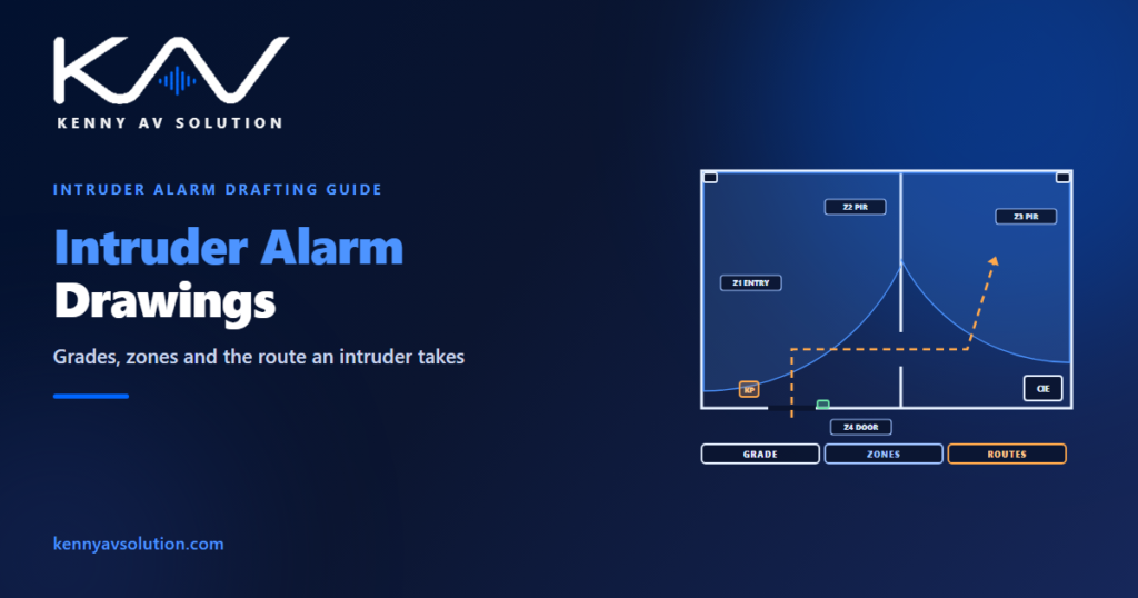
Intruder alarm drawings are, at heart, a plan of how someone would move through a building they should not be in. Where would they get in? Which way would they walk? What would they pass on the way to whatever is worth taking? A good drawing answers those questions first, then places detectors so the likely routes are covered — and shows its working so the installer, the insurer and the client can see why each device is where it is.
Intruder alarm requirements depend on the standards that apply and on what insurers and police response policies demand. In Europe the EN 50131 series is the reference, applied in the UK through PD 6662; other countries have their own. The examples below are illustrative; manufacturers’ data and the system designer govern.
Start with the grade, not the detectors
Under the EN 50131 series, a system is designed to a security grade from 1 to 4, from low risk to high risk, based on the kind of intruder expected and what is being protected. Equipment also has an environmental class, from indoor to outdoor conditions. The grade drives a great deal: the types of detector, the tamper protection, the signalling, the power supply standby.
Agree the grade with the client and, usually, their insurer before drawing anything, and put it on the drawings. A detector layout that is perfect for a grade 2 shop is not acceptable for a grade 3 warehouse full of high-value stock, and the difference shows up on the drawings, not just in the specification.
Zones and areas
An intruder alarm panel thinks in zones: each detector, or group of detectors, reports as a zone with a defined behaviour. Typical zone types include:
- Entry/exit — the door used to set and unset the system, which allows time to reach the keypad.
- Entry route — detectors along the path from that door to the keypad, which wait during the entry time.
- Intruder — everything else, which alarms immediately when the system is set.
- Personal attack or hold-up — buttons that alarm whether the system is set or not.
- Tamper — monitoring of the detectors, panel and wiring themselves.
Larger buildings are divided into areas that can be set separately — a warehouse set at night while the office is still in use. Show the zone number and type at every device on the plan, and list them in a zone schedule with location, device type and area, in the same way as any other device schedule. Use one numbering scheme across plans, schedules and wiring; see drawing standards.
Draw the route, not just the pattern
Most interior detection uses passive infrared (PIR) detectors, often combined with microwave in higher-risk or more demanding environments. A PIR’s coverage pattern looks like a fan on the plan, and it is tempting to fill the room with fans. The fan is not the whole story.
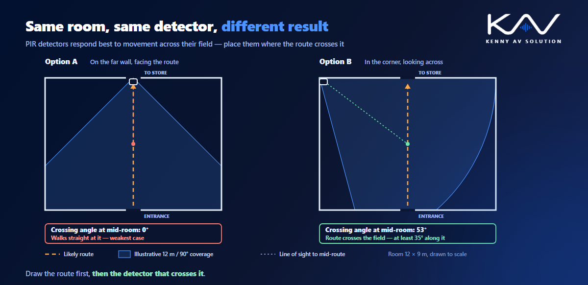
A PIR divides its field into zones and detects a warm body moving from one to the next. It is most sensitive to movement across its field and least sensitive to someone walking straight towards it, who stays within the same zones for longer. So the detector should be placed where the likely route crosses its field — often in a corner, looking across the room — rather than on the far wall staring back down the route.
That is why the drawing should show the expected routes — from doors and windows to the things worth protecting — as well as the coverage patterns, drawn to scale from the manufacturer’s data. Show obstructions such as high shelving and partitions that block the view, and note sources of false alarms: heaters and radiators in the field of view, direct sunlight, and moving objects such as blinds. Check positions on a site survey in existing buildings.
Doors, windows and the perimeter
Interior detectors catch someone who is already inside. Perimeter detection catches them on the way in: door contacts on external doors, sensors on vulnerable glazing, and, for some sites, external beams. Show each one on the plan with its zone.
Doors with access control often carry their own door contact. Decide whether the intruder alarm and the access control system share it or each have their own, and write the decision down; see access control drawings and the responsibility matrix. Where cameras cover the same entrances, coordinate with the CCTV coverage drawings.
Panel, keypads and wiring
Put the control panel inside the protected area, out of sight of the entrance, and the keypads at the entry/exit points, within easy reach of the person setting the system; heights follow the same logic as other user controls in wall elevations. Show the power supplies and their battery standby, which depends on the grade and the signalling; the calculation follows the same method as a fire alarm battery calculation.
Wiring diagrams should show each zone type’s connection, including the end-of-line arrangement the panel uses to detect tampering, and each cable should carry an ID on the cable schedule. Show how the system signals an alarm off site, typically to an alarm receiving centre, with the paths used.
Confirmation and response
Police and keyholder response increasingly depend on alarms being confirmed rather than single detector activations. In the UK, systems seeking police response generally have to follow BS 8243, using methods such as sequential confirmation — two separate detectors triggering in turn. That changes the design: detectors have to be arranged so that a genuine intruder will trigger two of them on any likely route. Show which detectors confirm which on the drawings, so the logic can be checked during the walk test at commissioning.
What an intruder alarm drawing set contains
- Design criteria: security grade, environmental class and response requirements.
- Floor plans with every detector, contact, keypad and personal attack button, each with its zone.
- Coverage patterns drawn to scale, with the expected intruder routes and obstructions.
- A zone schedule with zone number, type, location, device and area.
- Confirmation logic where alarms must be confirmed.
- Panel and power supply details with battery standby.
- Wiring diagrams for each zone type, and a cable schedule.
Frequently asked questions
What are EN 50131 security grades? Four grades, from 1 for low risk to 4 for high risk, describing the kind of intruder a system is designed to resist. The grade determines the types of detector, tamper protection, signalling and power supply required. The UK applies EN 50131 through PD 6662.
Where should a PIR detector be placed? Where the likely intruder route crosses its field of view, because PIR detectors are most sensitive to movement across their detection zones and least sensitive to someone walking straight towards them. A corner position looking across the room is often better than a far wall facing back down the route.
What zone types does an intruder alarm use? Typically entry/exit, entry route, intruder, personal attack or hold-up, and tamper. Each behaves differently when the system is set, and each device should show its zone number and type on the drawings.
What is a confirmed alarm? An alarm verified by more than one independent event, such as two separate detectors triggering in sequence. In the UK, systems seeking police response generally need to follow BS 8243, which sets out confirmation methods.
What should an intruder alarm zone schedule include? Each zone’s number, type, location, the device or devices on it, and the area it belongs to, using the same numbering as the floor plans and wiring diagrams.
Need intruder alarm drawings drafted?
Kenny AV Solution drafts intruder alarm documentation alongside AV, CCTV, access control and fire alarm systems for security contractors worldwide — detector and zone layouts with coverage patterns, zone schedules, panel and wiring diagrams and cable schedules, drawn to your standards and your title block. Send us the floor plans, the grade and the device list. See our drafting services, grab the free AV CAD Drafting Standards Checklist, or schedule a quick call — we come back with a quote and timeline within one business day.