
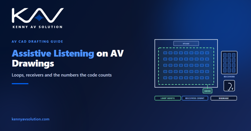
Assistive listening systems are the part of an AV design that the law is most likely to count. In many assembly spaces they are not a nice-to-have but a code requirement, with a minimum number of receivers, a share of them hearing-aid compatible, and signs telling people the system exists. An inspector or an accessibility reviewer can check all of that against the drawings — which means the drawings have to show it.
The requirements quoted here are from the 2010 ADA Standards for Accessible Design in the United States, as an example. State and local codes can add to them, and other countries have their own rules. Confirm what applies with the authority having jurisdiction on each project.
When assistive listening is required
Under the 2010 ADA Standards, an assistive listening system is required in each assembly area where audible communication is integral to the use of the space — lecture halls, auditoriums, theatres, council and meeting chambers, large training rooms. There is an exception where no audio amplification system is provided, but it does not apply to courtrooms, which need assistive listening either way; see courtroom AV drawings.
The standard then sets two numbers from the seating capacity: the minimum number of receivers, and how many of those must be hearing-aid compatible — meaning they work with a neckloop that couples to the telecoil in a hearing aid.
- Up to 50 seats: 2 receivers.
- 51 to 500 seats: 2, plus 1 for every 25 seats over 50.
- 501 to 1,000 seats: 20, plus 1 for every 33 seats over 500.
- 1,001 to 2,000 seats: 35, plus 1 for every 50 seats over 1,000.
- Over 2,000 seats: 55, plus 1 for every 100 seats over 2,000.
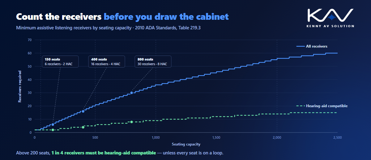
Up to 200 seats, 2 of the receivers must be hearing-aid compatible; above that, 1 in every 4. Fractions round up. So a 150-seat room needs 6 receivers, 2 of them hearing-aid compatible; a 400-seat auditorium needs 16, of which 4 are compatible; an 800-seat hall needs 30, of which 8 are. Where every seat is covered by an induction loop, the hearing-aid compatible count does not apply, because the loop itself serves telecoil users.
Choose the technology on the drawings, not in a spec line
“Assistive listening system” covers several technologies with very different drawing requirements. The choice should be made, and shown, at design.
- Induction loop (hearing loop) — a cable loop in the floor or ceiling creates a magnetic field that telecoil hearing aids pick up directly, so many users need no receiver at all. It is affected by steel in the building and can spill into adjacent rooms.
- Infrared — emitters flood the room with infrared light that receivers pick up. It stays inside the room, which suits confidential settings, but it needs line of sight and can be disturbed by strong sunlight.
- Radio frequency — easy to cover a large space, but the signal passes through walls, so it is a poor fit where privacy matters, and channels need coordinating between neighbouring rooms.
- Network or broadcast audio to personal devices — increasingly available, but check with the authority whether it counts toward the required receivers before relying on it.
Whichever is chosen, the source matters as much as the transmitter. Show on the signal flow diagram exactly which mix feeds the assistive listening system — usually a dedicated output from the processor, with speech, not a copy of the loudspeaker feed with all its room equalisation.
What an induction loop drawing needs
A loop is a piece of installed infrastructure, and it is drawn like one.
Show the loop route on the plan — a simple perimeter loop or a phased array of loops, depending on the room — with where the cable runs: in a floor chase, under the floor finish, or in the ceiling. Show the loop driver location and its feed from the processor, and the pathway between them. Note structural steel and reinforcement where it is known, because metal in the floor can weaken and distort the field; the site survey is where that gets captured on existing buildings. Mark the adjacent rooms where spill would matter, so the design can address it.
Loop performance is specified and measured to IEC 60118-4, which sets a reference field strength — 400 mA/m — and requires the field to stay within a tight tolerance across the listening area. State the standard on the drawing and mark the listening area, so the result can be measured during commissioning and verification.
What infrared and RF drawings need
For infrared, put the emitters on the reflected ceiling plan with their mounting heights and coverage footprints drawn, so you can see that every seat is inside one. Note windows and skylights facing the listening area. For RF, show the transmitter and antenna locations and the channel allocated, coordinated with any other RF systems in the building. Both need power at the emitter or transmitter, which belongs on the floor plans and RCPs like any other device.
Receivers are equipment, and they need a home
Receivers are counted, stored, charged and handed out, and the drawings should plan for that.
Put the receiver count — total and hearing-aid compatible — on the drawings, calculated from the seating capacity, rather than leaving it to the equipment list. Then show where the receivers live: a charging cabinet or rack with power, at the point where people collect them, such as a front desk, a box office or a technician’s position. A cabinet in a locked equipment room nobody visits is a cabinet nobody uses.
Signs, and the route a user actually takes
The 2010 ADA Standards also require signs informing people that assistive listening is available, using the international symbol of access for hearing loss, at the assembly area or at the ticket office where there is one.
Think about the route a user takes: where they learn the system exists, where they collect a receiver, and where they sit. Coordinate the sign locations with the architect’s signage drawings rather than assuming someone else will add them, and keep the collection point within reach and on an accessible route — the same reach-range thinking as in AV wall elevations.
What the drawings should show
- The technology chosen for each space, and why.
- The source on the signal flow: which output feeds the system.
- Loop routes and drivers, with pathways, known steel and spill-sensitive neighbours.
- Emitters or antennas on the RCP, with heights and coverage footprints.
- The listening area and the performance standard it is tested to.
- Receiver counts — total and hearing-aid compatible — from the seating capacity.
- Receiver storage and charging at the collection point, with power.
- Sign locations, coordinated with the architect.
Keep the symbols and tags consistent with your AV drawing standards, and include the system in the permit drawings where accessibility is reviewed.
Frequently asked questions
When is an assistive listening system required? Under the 2010 ADA Standards, in each assembly area where audible communication is integral to the use of the space. There is an exception where no audio amplification system is provided, but it does not apply to courtrooms. State and local codes can add requirements, and other countries have their own rules.
How many assistive listening receivers are required? Under the 2010 ADA Standards it depends on seating capacity: 2 for up to 50 seats, then 2 plus 1 per 25 seats over 50 up to 500 seats, with lower ratios for larger venues. For example, a 150-seat room needs 6 receivers and a 400-seat auditorium needs 16.
What does hearing-aid compatible mean for receivers? A receiver that works with a neckloop, which couples the audio magnetically to the telecoil in a hearing aid. Up to 200 seats, 2 receivers must be hearing-aid compatible; above that, 1 in every 4. The requirement does not apply where every seat is covered by an induction loop.
Which is better, a hearing loop, infrared or RF? It depends on the room. A loop lets telecoil users listen without a receiver but is affected by steel and can spill into adjacent rooms. Infrared stays in the room, which suits confidential spaces, but needs line of sight. RF covers large areas easily but passes through walls.
What standard applies to hearing loop performance? IEC 60118-4, which specifies a reference magnetic field strength of 400 mA/m and how evenly the field must be distributed across the listening area. The drawings should state the standard and mark the listening area so the installed loop can be measured against it.
Need assistive listening shown on your AV drawings?
Kenny AV Solution produces AV drawing sets in AutoCAD for integrators and consultants worldwide — floor plans and RCPs with loop routes and emitter coverage, signal flow showing the assistive listening feed, receiver counts and storage locations, and the rest of the set, drawn to your standards and your title block. Send us the architectural backgrounds, the seating layout and your equipment list. See our AV CAD drafting services, grab the free AV CAD Drafting Standards Checklist, or schedule a quick call — we come back with a quote and timeline within one business day.