
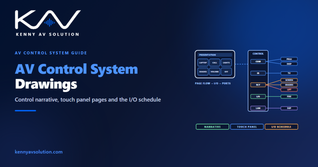
AV control system drawings are often the thinnest part of an AV set. The control processor appears as a box on the signal flow diagram with a few lines running out of it, and the real design — what each button does, which device is controlled how, what happens when the fire alarm goes off — lives in emails and in the programmer’s head. Then the programmer starts work, finds the projector lift needs two relays that the processor does not have, and the room is late.
Control protocols, port types and settings vary by manufacturer, and the device documentation governs. Interfaces with fire alarm and life-safety systems must be agreed with the fire alarm designer. The examples below are illustrative.
Start with a control narrative
A control narrative is a plain-language description of how the room works from the user’s side. It describes the room’s states — off, presentation, video call, shutdown — and what happens in each: which displays turn on, which source is selected, how the lights and shades respond, what the volume does, and what the system does when the room is empty or the fire alarm activates.
It is the most useful single document a programmer can receive, and the one most often missing. Write it before the drawings are finished, agree it with the client, and reference it from the drawings so the two stay together. Where many rooms share a standard, one narrative per room type is enough, with exceptions listed.
Draw the touch panel, not just its location
The user interface — usually a touch panel — is what the client actually sees. Show the page flow: the home page, source selection, video call, lighting and shades, and the shutdown confirmation, with arrows showing how the user moves between them. A simple wireframe of each page, with its buttons labelled, settles more arguments than any amount of email.
Keep the layout consistent across rooms of the same type, so a user who learns one room can use them all. The panel’s physical position, height and mounting belong on the wall elevations or the furniture details like any other user control.
The control I/O schedule
Every controlled device needs a line in a control I/O schedule: the device, how it is controlled, which port it connects to, and the settings needed to talk to it. Typical control methods are:
- IP — over the network, with an IP address or address range and the VLAN.
- RS-232 serial — with baud rate and other settings from the device’s documentation.
- IR — infrared emitters stuck on devices with no better control option.
- Relays — contact closures for screens, lifts, shades and other motors, often two per device for up and down.
- Contact inputs — signals into the processor, such as an occupancy sensor or a fire alarm contact.
Give every control cable an ID and put it in the cable schedule with the AV signal cables, and show the terminations on the point-to-point wiring diagrams.
Count the ports before drawing the cables
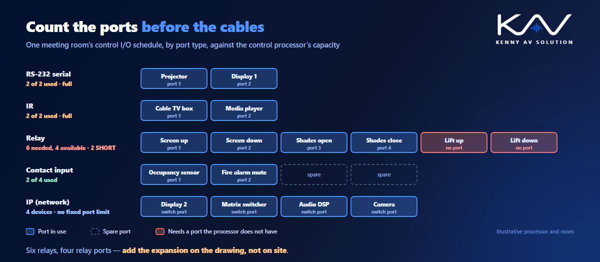
Once the schedule exists, add up the ports of each type and compare them with what the processor provides. It is the control equivalent of checking that no switcher input is used twice, and it catches the same kind of error: a design that cannot be built as drawn.
In the illustrative meeting room below, the serial and IR ports are exactly full and the contact inputs have room to spare, but the screen, shades and projector lift need six relays where the processor has four. The fix — a relay expansion module, an IP-controlled relay, or a lift controlled another way — belongs on the drawings, not on site.
Interfaces with other systems
The control system is where AV meets the rest of the building, and every interface needs both sides drawn:
- Lighting — scenes recalled from the touch panel, through the lighting control system; see lighting drawings.
- Fire alarm — a contact that mutes the audio or shuts the system down during an alarm, shown on both the AV and the fire alarm drawings.
- Occupancy and scheduling — sensors or room booking panels that wake or shut down the room.
- Shades, screens and lifts — often powered by the electrician and controlled by AV, which is exactly the kind of split to record in the responsibility matrix.
Control on the signal flow and network drawings
Show control connections on the signal flow diagram in their own line type and layer, so they can be read separately from audio and video. IP-controlled devices also belong on the AV network diagram, with their addressing and VLANs, and remote access to the control system should be covered in the network security documentation.
What a control system drawing set contains
- A control narrative for each room or room type.
- Touch panel page flow and page wireframes.
- A control I/O schedule with device, control method, port, settings and cable ID.
- A port count against the processor’s capacity, with any expansion shown.
- Control connections on the signal flow, in their own line type.
- Network details for IP control: addresses, VLANs and switch ports.
- Interface details with lighting, fire alarm, shades and occupancy, drawn on both sides.
At commissioning, test every button against the narrative and every interface against the schedule.
Frequently asked questions
What is an AV control narrative? A plain-language description of how an AV system works from the user’s side: the room states, what each button does, how lighting, shades and volume respond, and what happens when the room is empty or the fire alarm activates. It is written before programming starts and agreed with the client.
What should a control I/O schedule include? Every controlled device, its control method such as IP, RS-232, IR, relay or contact input, the processor port it connects to, the settings needed to communicate with it, such as baud rate or IP address, and the cable ID.
How do you check that a control processor has enough ports? Add up the ports needed of each type from the control I/O schedule and compare them with the processor’s capacity. Any shortfall is solved on the drawings, for example with an expansion module or by controlling a device over the network instead.
Should touch panel layouts be on the AV drawings? Yes. A page flow and simple wireframes of each page, with labelled buttons, let the client approve the interface before programming and keep rooms of the same type consistent.
How is a fire alarm interface shown on AV drawings? As a contact from the fire alarm system into the AV control processor or audio processor, shown on both the AV and the fire alarm drawings, with the action it triggers, such as muting audio or shutting the system down, stated in the control narrative.
Need AV control system documentation?
Kenny AV Solution drafts AV documentation for integrators, consultants and programmers worldwide — control I/O schedules, touch panel page layouts, signal flow with control connections and interface details, drawn to your standards and your title block. Send us the equipment list and the room requirements. See our drafting services, grab the free AV CAD Drafting Standards Checklist, or schedule a quick call — we come back with a quote and timeline within one business day.