
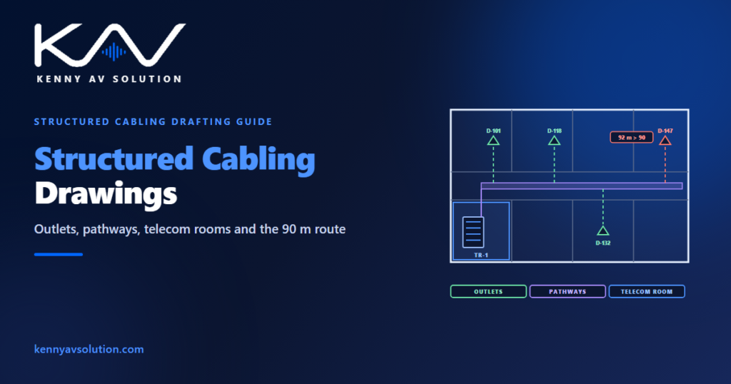
Structured cabling drawings carry the network that almost every other low-voltage system now depends on. Displays, codecs, wireless access points, cameras, door controllers and phones all end at a data outlet, and every outlet ends at a patch panel in a telecom room. Draw that system well and every trade can find its connection. Draw it as a scatter of triangles on a floor plan and the cabling installer has to design it on site, usually without the 90-metre limit in mind.
Structured cabling is governed by the ANSI/TIA-568 series in North America, with TIA-569 for pathways and spaces, TIA-606 for labelling and administration, and TIA-607 for bonding. ISO/IEC 11801 and EN 50173 cover the same ground internationally. The figures below are illustrative; the standards, the designer and the client’s IT requirements govern.
A system, not a pile of cables
Structured cabling follows a fixed hierarchy, and the drawings should show it:
- Entrance facility — where the service providers’ cables enter the building.
- Equipment room or main distribution frame (MDF) — the building’s core network equipment.
- Telecom rooms or intermediate distribution frames (IDFs) — one or more per floor, serving the outlets near them.
- Backbone cabling — usually fibre, sometimes with copper, linking the MDF and the telecom rooms.
- Horizontal cabling — from a patch panel in a telecom room to each outlet.
- Work area outlets — where devices and patch cords plug in.
Each level appears on a different drawing: the outlets on floor plans, the routes on pathway plans, the rooms on enlarged plans and rack elevations, and the backbone on a riser diagram.
Outlet plans: every port, with its identity
The outlet plan is the drawing the installer works from most. Show every outlet with its identifier, its number of ports and its type: a desk data outlet, a ceiling outlet for a wireless access point, a camera outlet, an outlet behind a display. State the mounting — wall, floor box, ceiling or furniture — and the height, so the outlet matches the wall plate details and wall elevations.
Many of the outlets belong to other systems. Network cameras come from the CCTV drawings, door controllers from the access control drawings, codecs and displays from the AV design. Coordinate them before issue, and record who provides each cable in the responsibility matrix, so a camera outlet is neither left out nor installed twice.
Measure the route, not the plan
The best-known number in structured cabling is the length limit. Under TIA-568 a twisted-pair horizontal permanent link — from the patch panel to the outlet — may be no longer than 90 m (295 ft), and the complete channel, including patch cords at both ends, no longer than 100 m.
The trap is measuring it on the plan. The cable does not run in a straight line. It rises from the rack to the ceiling, follows the cable tray along corridors, turns into each room, and drops down the wall to the outlet. Installers also leave service loops at both ends. An outlet that looks 64 m from the telecom room on the plan can need more than 90 m of cable.

Draw the pathways
Because the length depends on the route, the drawings should show the route. Show the cable tray, conduit and J-hook runs with their sizes, the sleeves through walls and floors, and the firestopping at rated penetrations. Coordinate the tray with the ductwork, sprinklers and lighting in the ceiling void; see trade coordination. Size the pathways for the cable count plus room to grow, and show the conduit from each outlet box to the tray.
Where routes are too long, the drawings must show the fix: another telecom room closer to the outlets, or a fibre link to a remote enclosure. Moving the telecom room after the walls are built is much harder than drawing it in the right place.
Telecom rooms: plans and rack elevations
Each telecom room needs an enlarged plan and rack elevations. The plan shows the racks or cabinets, the clearances in front of and behind them, the door, the wall-mounted backboard, the cable entry, the ladder rack above, and the bonding busbar; see grounding and bonding. The elevations show every patch panel, switch, cable manager and power unit by rack unit, with the panel and port identifiers.
Network switches bring power and heat, especially when they power cameras, access points and displays over Ethernet. Show the dedicated circuits and the cooling the room needs, using the same method as an AV rack power and heat calculation.
The backbone on a riser diagram
A riser diagram shows how the equipment room connects to every telecom room: the number and type of fibre strands and any copper pairs on each backbone link, the routes between floors, and the entrance facility. It is the simplest drawing in the set and the one the IT team reads first. Draw it in the same way as an AV conduit and riser diagram, with the vertical pathways sized for future capacity.
Labels, tests and as-builts
TIA-606 sets out how to identify telecom spaces, racks, panels, ports and cables so that every link can be traced. Use it or the client’s own scheme, but use one scheme everywhere: the identifier on the outlet plan, the label on the faceplate, the patch panel port and the test report must all match. Put the format in the legend; see drawing standards.
Every installed link is certified with a tester against the performance category and the permanent link or channel limits. The results are keyed to those identifiers, which is why the identifiers have to be fixed before installation. After testing, record any changed routes or outlet positions on the as-built drawings.
What a structured cabling drawing set contains
- A legend and general notes with the standards, the cable category, the identifier format and the testing requirements.
- Outlet plans with every outlet’s identifier, port count, type, mounting and height.
- Pathway plans with tray, conduit, J-hooks, sleeves and firestopping.
- Enlarged telecom room plans and rack elevations with panels and ports.
- A riser diagram for the backbone.
- A bonding diagram for the telecom rooms.
- Schedules of outlets and links, in the same format as a cable schedule.
Frequently asked questions
What is the maximum length of a structured cabling run? Under TIA-568, a twisted-pair horizontal permanent link from the patch panel to the outlet can be up to 90 m (295 ft), and the full channel including patch cords up to 100 m. The length is measured along the actual cable route, including vertical rises, drops and service loops, not as a straight line on the plan.
What should a structured cabling drawing set include? Outlet plans with identifiers and types, pathway plans with tray and conduit, enlarged telecom room plans, rack elevations, a backbone riser diagram, a bonding diagram, and schedules of outlets and links, with a legend stating the standards, cable category and labelling format.
What is the difference between an MDF and an IDF? The main distribution frame, or equipment room, holds the building’s core network equipment and the connection to service providers. Intermediate distribution frames, or telecom rooms, are placed around the building and serve the outlets near them, linked back to the MDF by backbone cabling.
What is TIA-606? The ANSI/TIA standard for the administration of telecommunications infrastructure. It defines how to identify and label spaces, racks, patch panels, ports and cables, so every link can be traced from the outlet to the panel and matched to its test results.
Why do outlets need identifiers on the drawings? Because the same identifier is used on the faceplate label, the patch panel port, the test report and the as-built drawings. Fixing the identifiers on the drawings before installation is what makes every link traceable afterwards.
Need structured cabling drawings drafted?
Kenny AV Solution drafts structured cabling documentation alongside AV, CCTV, access control and other low-voltage systems for integrators and contractors worldwide — outlet and pathway plans, telecom room layouts, rack elevations, riser diagrams and schedules, drawn to your standards and your title block. Send us the floor plans and the outlet requirements. See our drafting services, grab the free AV CAD Drafting Standards Checklist, or schedule a quick call — we come back with a quote and timeline within one business day.