
Broadcast studio AV drawings describe a system where everything is connected to everything else, and most of it has to agree on time. In a meeting room, a signal goes from a source to a display and the job is done. In a studio, a camera feeds a switcher that feeds a recorder, a stream, a multiviewer and a return to the floor, while an intercom links a dozen people and a tally light tells the presenter which camera is live. The drawings are what let anyone trace that web after the installer has gone home.
This covers production studios built by integrators — corporate, university, church media and streaming studios. A broadcaster’s own facilities are governed by that broadcaster’s engineering standards, acoustic isolation is designed by the acoustician, and loads on a lighting grid are the structural engineer’s to approve. What follows is what AV has to document.
Everything has to agree on time
This is the concept with no equivalent elsewhere in AV, and it deserves its own drawing.
When a switcher cuts between two cameras, both signals have to arrive in step, or the cut glitches. In a traditional SDI studio that is achieved with a common reference: a sync generator produces a timing signal — black burst for standard definition, tri-level sync for HD — and distribution amplifiers deliver it to every camera, switcher, recorder and converter that needs to lock to it. Timecode is often distributed alongside it, so that everything recorded can be lined up afterwards.
In an IP studio built on SMPTE ST 2110, the reference becomes a network service. Devices lock to Precision Time Protocol distributed from a grandmaster clock, and the network switches in between have to handle PTP properly. The timing is now carried by the network, which means the network design is part of the timing design.
Either way, draw the reference distribution as its own diagram: the source, the distribution, and every device that locks to it. It is invisible on an ordinary signal flow diagram, because it carries no picture, and it is the first thing anyone checks when an image jumps on a cut. For an IP facility, the AV-over-IP network diagram has to show where the grandmaster sits and how timing reaches the edge.
The jackfield is the drawing people actually use
Every studio has patch bays — jackfields for video, patchbays for audio — and they are the one part of the documentation the operators read every day.
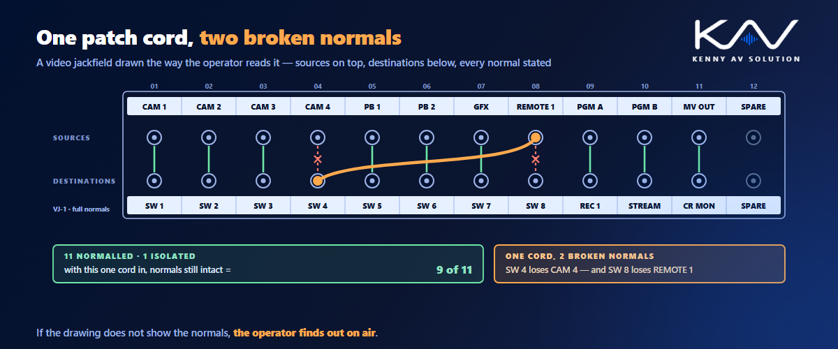
A jackfield lets an operator reroute a signal with a patch cord instead of rewiring. By convention the top row carries sources and the bottom row carries destinations, and most pairs are normalled: with no cord in, the source feeds its usual destination automatically. The designation strips above and below the jacks are therefore not decoration. They are the interface.
What the drawing has to state, for every column, is the source, the destination, whether the pair is normalled, and what inserting a cord does. That last point is where studios get caught. On a fully normalled video jackfield, a cord in either jack breaks the normal — so one cord patched from one column to another can quietly disconnect two unrelated feeds. Audio patchbays are often half-normalled, where a cord in the top row takes a copy without breaking anything. If the drawing does not say which is which, the operator discovers it live.
So draw each jackfield as an elevation, designation strips included, with the normalling stated per column and the jack numbers tying back to the cable schedule. It is the studio equivalent of a rack elevation, and it will be printed and taped to the wall beside the bay.
Wall boxes are the studio floor’s interface
The studio floor is empty space that gets reconfigured for every production. Cameras, microphones, monitors and lighting move; the connections they plug into do not.
Those connections live in wall boxes and floor pockets around the perimeter: a panel of camera connections, audio lines, video returns, intercom, data and power in a known place. They are the only fixed points on the floor, and each one needs a panel elevation showing every connector, its number and where it goes.
The numbering is what makes the studio traceable. A connector on wall box B should carry a reference that appears on the jackfield designation strip and in the cable schedule, so a fault on the floor can be followed all the way back to the equipment room. A studio where the wall box says one thing, the jackfield says another and the schedule says a third is a studio where every fault takes an afternoon.
Where cameras and lighting positions are fixed rather than roaming, they also belong on the plan and the reflected ceiling plan together. That coordination is the one covered in house of worship AV drawings, and it applies here unchanged.
Intercom and tally are systems of their own
These two are the most frequently under-documented parts of a studio, because neither carries picture or programme sound.
Intercom — talkback — connects the director, the camera operators, the floor manager, audio, graphics and anyone else who needs to talk during a production. A simple studio might use a party-line system; a larger one uses a matrix, where each panel has keys routed to specific people or groups. The talent often hears a separate feed in an earpiece, interruptible foldback, so the director can speak over the programme audio. Draw intercom as its own diagram: every station, every beltpack, what each key talks to, and where the IFB feeds go.
Tally is the red light that tells a camera operator and a presenter which camera is on air. It is a logic signal from the switcher to every camera, monitor and multiviewer that needs to show it. It is simple, and it is exactly the kind of simple thing that gets left off a drawing and then wired inconsistently. Show the tally source, the interface, and every device that receives it.
The control room sees everything at once
A studio control room is not a meeting room with extra screens. Its whole purpose is to let a small number of people see and hear everything happening at the same time.
That makes monitoring a design deliverable. The multiviewer layout — which source sits in which tile, where programme and preview appear, where tally and audio meters show — is something operators will look at for every hour of every production, and it should be drawn and agreed rather than configured on the day. The same goes for audio monitoring: what each position hears, and how.
The physical room follows the same principles as any control room — consoles, sightlines to the monitor wall, the equipment behind. What is specific to a studio is the relationship with the floor: whether there is a window, what the director can see through it, and which cameras need a clean sightline from the gallery.
At a stadium, broadcast is somebody else’s system and the job is to document the hand-off, as described in stadium and arena AV drawings. In a studio there is no hand-off. The broadcast chain is the system, all the way from the lens to the stream encoder.
Sound isolation is designed before AV arrives
A studio has to be quiet, and quiet is expensive. Serious studios are built as a room within a room, with floating floors, isolated walls and ceilings, and ventilation designed to be silent. The acoustician designs that envelope, and every hole through it is a potential leak.
AV needs a lot of holes. Camera cables, audio lines, video returns, intercom, data and power all have to cross from the floor to the control room and the equipment room. The answer is to use designed entry points rather than drilling where convenient: sleeves, acoustic cable transits or dedicated panels that the acoustician has agreed and detailed. Every crossing of the acoustic envelope belongs on the drawing as a named item with its treatment.
Plan for more capacity than the first production needs. Studios grow — another camera, a second set, a remote contribution — and once the envelope is sealed, adding a route through it means re-opening something the acoustician built. Spare sleeves and pull cords cost nothing at the start. The same thinking applies to the containment between the studio, the control room and the equipment room.
What a studio AV set contains
A conventional set, with several diagrams that exist only in a studio:
- Floor plans and RCPs for studio, control room and equipment room, with wall box locations.
- Signal flow diagrams for video and audio, from source to switcher to every destination.
- A reference distribution diagram: sync or PTP, and every device that locks to it.
- Jackfield and patchbay elevations with designation strips and normalling per column.
- Wall box and floor pocket panel elevations, each connector numbered and traced.
- An intercom diagram with every station, key assignment and IFB feed.
- A tally diagram from the switcher to every camera, monitor and multiviewer.
- Multiviewer and monitoring layouts agreed with the operators.
- Acoustic envelope penetrations, each with its approved treatment.
- Rack elevations and a cable schedule whose numbering matches the jackfields and wall boxes.
- As-builts, because studios are re-patched and extended constantly.
Keep the conventions consistent with your documented AV drawing standards, and treat the acoustician, lighting designer and structural engineer as the interfaces described in AV trade coordination. When the build is done, an accurate as-built set is what keeps the patching understandable as the studio changes.
Frequently asked questions
What makes broadcast studio AV drawings different from other AV drawings? The number of interconnected systems and the need for them all to agree on time. A studio needs diagrams most AV projects never have — reference distribution, jackfield elevations with normalling, wall box panels, intercom, tally and multiviewer layouts — and the numbering has to trace consistently from the floor to the equipment room.
What is genlock and why does it need its own drawing? Genlock locks cameras, switchers and recorders to a common timing reference so that sources can be cut between cleanly. In an SDI studio the reference is black burst or tri-level sync from a sync generator; in an SMPTE ST 2110 studio it is Precision Time Protocol from a grandmaster clock. It carries no picture, so it does not appear on an ordinary signal flow diagram and needs a diagram of its own.
What does normalled mean on a jackfield? A normalled pair connects its source to its usual destination with no patch cord in place. On a fully normalled video jackfield, a cord in either jack breaks that connection, so a single cord can break two normals at once. Half-normalled audio patchbays let a cord take a copy from the top row without breaking anything. The drawing should state the normalling for every column.
Why document intercom and tally separately? Because neither carries picture or programme sound, so both are easy to omit from signal flow diagrams and then wire inconsistently. Intercom needs every station, key assignment and IFB feed shown; tally needs the path from the switcher to every camera, monitor and multiviewer that displays it.
How should cables cross a studio’s acoustic isolation? Through designed entry points agreed with the acoustician — sleeves, acoustic transits or dedicated panels — never by drilling where convenient. Every crossing of the acoustic envelope should be a named item on the drawing with its treatment, and spare capacity should be provided because adding routes after the envelope is sealed is disruptive.
Need studio AV drawings drafted?
Kenny AV Solution produces AV drawing sets in AutoCAD for integrators and consultants worldwide — studio and control room plans, signal flow and reference distribution diagrams, jackfield and patchbay elevations with designation strips, wall box panels, intercom and tally diagrams, multiviewer layouts, rack elevations, cable schedules and as-builts, drawn to your standards and your title block. Send us the room layout and your system design, and we will produce a set the operators can patch from. See our AV CAD drafting services, grab the free AV CAD Drafting Standards Checklist, or schedule a quick call — we come back with a quote and timeline within one business day. For the underlying documentation standards, AVIXA is the reference worth having on the shelf.