
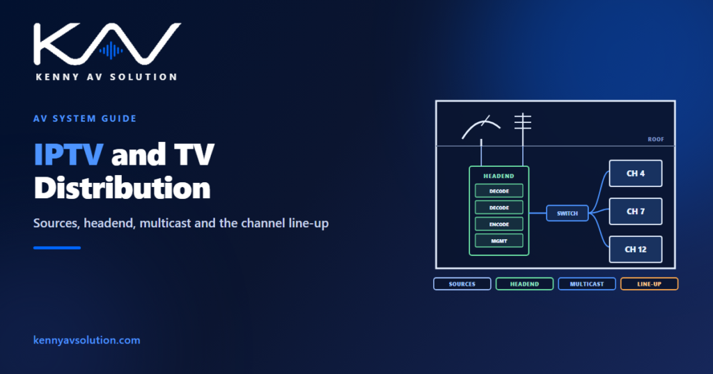
IPTV and TV distribution drawings document how television channels get from an aerial, a satellite dish or a provider’s feed to every screen in a building. Hotels, hospitals, stadiums, student accommodation, offices and bars all need it, and it is usually somebody’s afterthought until the screens are on the walls and nothing is playing. A TV system has three parts — the sources, the headend and the distribution — and the drawings need to show all three, plus the network decisions that make IPTV work at scale.
Content licensing, encryption and the rights to show broadcast television in commercial premises are set by the channel providers and local law; confirm them with the client and provider. Products, bitrates and network settings vary, and the manufacturer’s documentation governs. Figures below are illustrative.
Sources: where the channels come from
- Terrestrial — an aerial on the roof, receiving local broadcast channels.
- Satellite — one or more dishes, each needing a clear view of the sky in a fixed direction, structural support and bonding.
- Provider feeds — a cable or IPTV service delivered by a provider into the building.
- Internal channels — the building’s own content: welcome channels, digital signage, live feeds from a chapel, a lecture theatre or a pitch.
Roof-mounted dishes and aerials go on the roof plan with their position, mounting, cable route and earthing, coordinated with the structural engineer and the grounding and bonding design.
The headend
The headend turns the sources into channels the building can distribute: receivers and decoders for each source, encoders that convert channels into IP streams, and the management system that controls the channel line-up, the programme guide and the screens. It usually lives in a rack in a communications or equipment room, drawn as a rack elevation with its power and heat, and as a block diagram from sources to outputs.
Distribution: IPTV or RF
Older systems distribute channels as RF over coaxial cable, like a domestic aerial system scaled up. Most new systems use IPTV: each channel becomes a multicast stream on the building network, and each screen joins the stream it wants. IPTV uses the same structured cabling as everything else and scales well, but it puts real load on the network, so the network design has to be part of the TV design.
Multicast is the network decision that matters
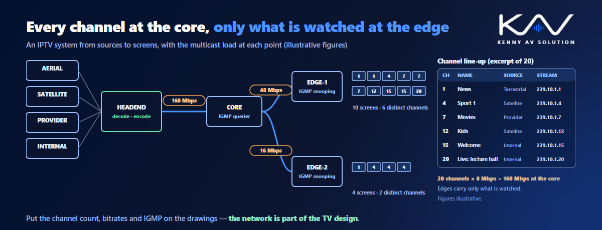
Every IPTV channel is a continuous stream. Without the right switch configuration, every stream can be flooded to every port on the network, which overwhelms it. With IGMP configured — a querier, and snooping on the switches — each switch only forwards the channels its screens have actually asked for. The uplink to an edge switch then carries only the channels being watched on that switch, not the whole line-up. The same principles are covered in AV over IP network diagrams.
An illustrative example: a line-up of 20 channels at about 8 Mbps each is roughly 160 Mbps if every channel crosses the core. An edge switch serving ten screens tuned to six different channels only needs those six streams — about 48 Mbps — however many screens share them. Without IGMP, that same switch would receive all 160 Mbps on every port that floods.
Put the numbers on the drawings: the number of channels, the bitrate of each, the worst-case load on the core and the expected load on each edge switch. Agree the multicast addressing, the VLAN and who configures the switches with IT, and record it alongside the network security documentation.
The channel line-up
A channel line-up table is to a TV system what a frequency plan is to wireless microphones: channel number, name, source, stream address and bitrate. It is the document the client checks, the provider confirms and the installer programmes from, so keep it on the drawings and under revision control.
Screens and outlets
Each screen needs power and a network connection in the right place, behind the display, plus a set-top box or a commercial TV with a built-in IPTV client. Show the outlets on the plans and elevations with mounting heights, and list the screens in the device schedule with their type and location. In repeated rooms — guest rooms, patient rooms, student rooms — draw one typical and use a room schedule, as in hotel AV drawings.
Frequently asked questions
What is an IPTV system? A system that distributes television channels as data streams over a building’s network, so screens can select channels without a separate coaxial cable network. Channels are usually sent as multicast streams that screens join on demand.
What is a TV headend? The equipment that receives the channels from aerials, satellite dishes or provider feeds, decodes them and converts them into channels the building can distribute, together with the system that manages the channel line-up and the screens.
Why does IPTV need IGMP? Because each channel is a continuous multicast stream. IGMP snooping, with a querier on the network, lets switches forward only the channels that connected screens have requested, instead of flooding every stream to every port.
What should a channel line-up include? Each channel’s number, name, source, stream address and bitrate. It is checked by the client, confirmed with the provider and used by the installer to programme the system.
Can a business show broadcast TV on its screens? It depends on the provider’s terms and local law, which often treat commercial premises differently from homes. Confirm the licensing with the client and the provider before the system is designed.
Need IPTV and TV distribution drawings?
Kenny AV Solution drafts AV documentation for integrators, consultants and design-build teams worldwide — headend block diagrams and rack elevations, IPTV network diagrams with multicast and VLANs, channel line-ups, roof plans for dishes and aerials, and screen outlet plans with typical rooms, all drawn to your standards and your title block. See our drafting services, get an existing set checked with a drawing set review, or schedule a quick call — we come back with a quote and timeline within one business day.