
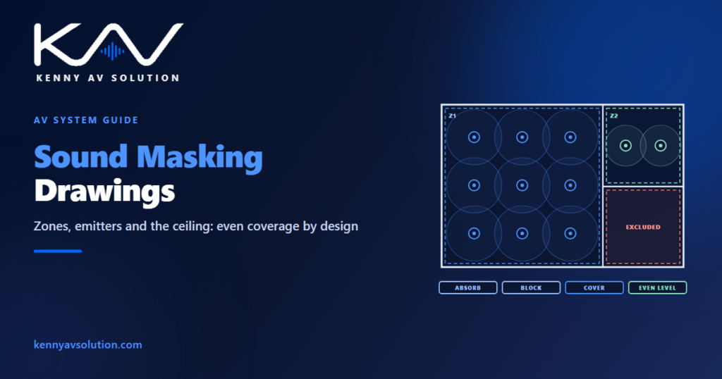
Sound masking drawings document a system whose whole job is to be unnoticed. Sound masking adds a low, even background sound to a space — shaped to cover the frequencies of speech, not the hiss of white noise — so that conversations a few desks away become less intelligible and less distracting. It is common in open-plan offices, healthcare, banks, legal offices and courtrooms. Done well, nobody knows it is there. Done badly, it is either inaudible and useless or uneven enough that people notice the hiss and complain. Most of the difference is decided on the reflected ceiling plan.
Masking levels, spectrum, emitter spacing and coverage depend on the product and the space, and the manufacturer’s documentation and the project’s acoustician govern. Interfaces with the fire alarm must be agreed with the fire alarm designer. The examples below are illustrative.
Masking is one part of speech privacy
Acousticians often describe speech privacy in three parts: absorb sound with ceiling tiles and soft finishes, block it with walls, screens and full-height partitions, and cover what is left with masking. Masking only does the third. It will not make a room with a hard ceiling and no partitions private, and it should not be drawn as if it will. Where there is an acoustician, their report sets the target; the drawings show how the system meets it.
Emitters on a grid, not a guess
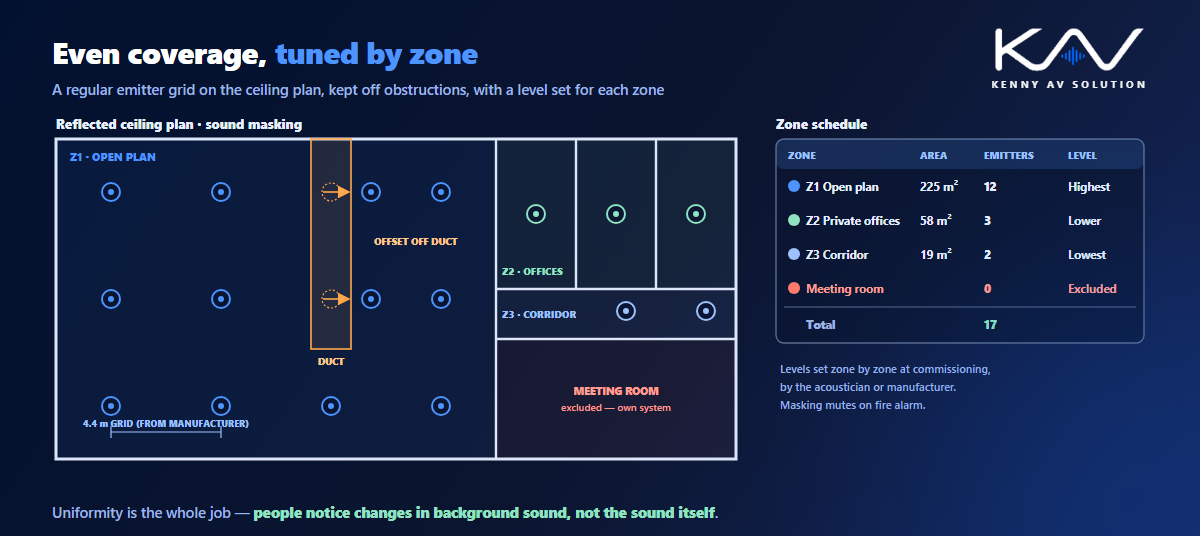
The single most important property of a masking system is uniformity. People notice changes in background sound far more than the sound itself, so the level has to be even as someone walks through the space. That is why emitters are laid out on a regular grid across the reflected ceiling plan, with the spacing taken from the manufacturer for the ceiling height, ceiling type and plenum depth — not placed one per room, and not wherever there happens to be a gap between the lights.
- In-plenum systems point the emitters up into the space above the ceiling, so the sound spreads and comes through the tiles evenly.
- Direct-field systems point the emitters down into the room, through the ceiling or from exposed structure where there is no ceiling at all.
State which type is used, because it changes the spacing, the mounting and what the ceiling contractor needs to know. Like any ceiling device, the emitters share the plan with lights, diffusers, sprinklers and loudspeakers; the coordination rules in AV floor plans vs reflected ceiling plans apply here too.
The plenum decides more than you expect
An in-plenum system relies on the ceiling void. Ducts, beams, cable trays and changes in plenum depth all affect how the sound spreads, and a grid that looks perfect on a plan can be blocked by a large duct in reality. Note the plenum depth and the major obstructions on the drawings, shift emitters off ductwork rather than mounting them on it, and flag areas where the ceiling changes type or height. The ceiling-void checks in the AV site survey are the same ones that matter here. Cable run through an air-handling plenum normally needs to be rated for it, so say so on the plan.
Zones are where the tuning happens
Different spaces need different levels. An open-plan area needs more masking than a private office, a corridor needs less, and a meeting room is often excluded or given its own zone. Draw the zones on the plan, give each a name, and list them in a zone schedule: the zone, the area it covers, the number of emitters, and the target level set by the acoustician or the manufacturer.
Smaller zones are easier to tune evenly, because the level is set zone by zone during commissioning with a sound level meter, walking the space. A zone that covers both an open-plan area and a row of offices will be wrong for one of them.
Paging, music and the fire alarm
Many masking systems also carry paging and background music through the same emitters or loudspeakers. If they do, show the inputs, the zones that receive each source and the priority between them, as with any paging system. And show what happens when the fire alarm activates: masking is normally muted so that voice alarm messages and alarms are heard clearly. Draw that interface on both the masking and the fire alarm drawings, and record who provides it in the responsibility matrix.
What the drawing set contains
- A reflected ceiling plan with every emitter, the grid spacing, the zone boundaries and zone names, ceiling type and plenum depth.
- A zone schedule with area, emitter count and target level per zone.
- A riser or block diagram from the controller to each zone, with cable types and the paging, music and fire alarm inputs.
- The controller and amplifier positions, in the rack or wall-mounted, with their power on the rack power schedule.
- Notes on commissioning: who sets the levels, how they are measured and how the results are recorded for verification.
Frequently asked questions
What is sound masking? A system that adds a low, even background sound, shaped to cover the frequencies of human speech, so that nearby conversations are less intelligible and less distracting. It improves speech privacy alongside absorption and physical barriers.
What do sound masking drawings show? A reflected ceiling plan with every emitter, the grid spacing, zone boundaries, ceiling type and plenum depth; a zone schedule with emitter counts and target levels; and a riser diagram from the controller to each zone, including any paging, music and fire alarm interfaces.
How far apart are sound masking emitters? It depends on the product, ceiling height, ceiling type and plenum depth, so the spacing comes from the manufacturer. What matters is a regular grid that produces an even level across the space.
What is the difference between in-plenum and direct-field sound masking? In-plenum emitters face up into the ceiling void, so the sound spreads and comes through the ceiling tiles. Direct-field emitters face down into the room, which suits spaces with exposed structure or no suspended ceiling.
Should sound masking mute on fire alarm? Normally yes, so that voice alarm messages and alarm signals are clearly heard. The interface should be agreed with the fire alarm designer and shown on both the masking and fire alarm drawings.
Need sound masking drawings?
Kenny AV Solution drafts AV documentation for integrators, consultants and design-build teams worldwide — masking emitter layouts and zone plans on the reflected ceiling plan, zone schedules, riser diagrams with paging and fire alarm interfaces, and the rest of the AV set, all drawn to your standards and your title block. See our drafting services, get an existing set checked with a drawing set review, or schedule a quick call — we come back with a quote and timeline within one business day.