

Fire alarm drawings are reviewed more closely than almost any other low-voltage set. They go to the authority having jurisdiction for plan review, and the reviewer does not just look at the symbols: they check the spacing, the ratings, the battery calculation and the voltage drop. A set that is neat but does not show its arithmetic comes back with comments. A set that shows its working usually gets through.
Fire alarm design is life-safety work. The system is designed by a qualified designer under the codes that apply — in the United States usually NFPA 72 with the building and fire codes adopted locally, in the UK BS 5839-1, elsewhere the EN 54 family and national rules — and approved by the authority. The figures below are illustrative examples of the documentation, not design values; the manufacturer’s data and the designer of record govern.
What a fire alarm submittal contains
In the United States, NFPA 72 includes a documentation chapter that sets out what shop drawings should contain. Other standards differ in detail, but a complete submittal generally includes:
- Floor plans showing every initiating device and notification appliance, with ratings, addresses or circuits.
- A riser diagram showing the panel, the circuits and how they run through the building.
- A sequence of operations — what each input causes to happen.
- Battery calculations for the panel and every power supply.
- Voltage drop calculations for the notification circuits.
- Equipment data sheets and wiring details.
Most of that is drafting, and all of it has to agree. A device on the plan that is missing from the battery calculation is exactly the kind of inconsistency a reviewer finds first.
Device plans: draw what the reviewer measures
A reviewer checks a fire alarm plan with a scale rule and the code, so the plan has to give them what they need.
Show every device with its type and rating next to the symbol — the candela rating beside each strobe, the detector type beside each detector — and its address or circuit. Show ceiling heights and anything that affects coverage, such as deep beams, soffits and sloped ceilings, because detector and appliance spacing depends on them. Mounting heights for wall-mounted appliances belong on the plan or a typical elevation.
Fire alarm devices share the ceiling with lights, sprinklers, diffusers and AV loudspeakers, so the plans should be coordinated with the reflected ceiling plans of the other trades before they are issued; see trade coordination.
The riser: the whole building on one sheet
The riser diagram shows the system as a whole: the main panel, any remote power supplies and annunciators, the signalling line circuits that carry the addressable devices, the notification circuits that drive the horns, strobes or speakers, and how each circuit runs from floor to floor.
It is also where the interfaces appear: elevator recall, HVAC shutdown, door holders, access control release — and the AV system. In many buildings the fire alarm signals the AV and paging systems to mute or shut down so that alarm messages are heard. That interface belongs on both sets of drawings, on the fire alarm riser and on the AV signal flow, with who provides each side stated, as described in the AV responsibility matrix. Pathways and riser routes follow the same logic as conduit and riser diagrams, with any survivability requirements for the circuits noted.
Battery calculations: show every line
When mains power fails, the batteries have to run the system in standby for a set period and then power it in alarm. Under NFPA 72, a typical fire alarm system needs 24 hours of standby followed by 5 minutes of alarm; emergency voice systems need longer in alarm, and BS 5839-1 and other standards set their own durations.
The calculation multiplies the standby current by the standby time, adds the alarm current multiplied by the alarm time, and applies a safety margin. An illustrative example:
| Item | Current | Time | Capacity |
|---|---|---|---|
| Standby (panel and all devices) | 0.35 A | 24 h | 8.40 Ah |
| Alarm (panel, devices and appliances) | 3.20 A | 5 min | 0.27 Ah |
| Subtotal | 8.67 Ah | ||
| With 20% margin | 10.40 Ah | ||
| Battery specified | 12 Ah |
Every device on the plans should appear in the currents, with the manufacturer’s figures for each. The margin used varies by manufacturer and practice; state it rather than burying it.
Voltage drop: the last appliance has to work
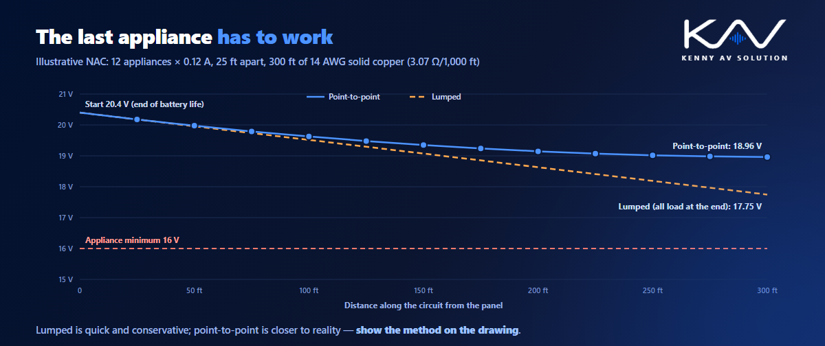
Notification appliances need a minimum voltage to operate, typically stated by the manufacturer — 16 V is a common figure for 24 V appliances. The calculation starts from the voltage the panel can be relied on to deliver at the end of battery life, often taken as 20.4 V for a 24 V system, and subtracts the drop along the wire.
There are two common methods. The lumped method assumes the whole load sits at the far end of the circuit: quick, simple and conservative. The point-to-point method calculates the drop segment by segment, with the current falling as each appliance takes its share: more work, but closer to reality, and it can save a circuit or a heavier cable when the lumped result is marginal.
In the illustrative example in the chart, 12 appliances drawing 0.12 A each are spaced 25 ft apart on a 300 ft run of 14 AWG solid copper, about 3.07 ohms per 1,000 ft of conductor from the NEC Chapter 9 resistance table. The lumped method predicts 17.75 V at the last appliance; point-to-point predicts 18.96 V. Both clear 16 V. Whichever method is used, put it on the drawing with the inputs, so the reviewer can repeat it.
The sequence of operations
A fire alarm system is defined as much by what it does as by what it contains. The sequence of operations — often a matrix with inputs down the side and outputs across the top — states what each device or event causes: which appliances activate, which doors release, which fans stop, which lifts recall, and whether the AV system mutes. It is the document the system is tested against at acceptance, as with commissioning and performance verification for AV.
What a complete fire alarm drawing set contains
- Floor plans with every device, its type, rating and address or circuit, and ceiling heights.
- A riser diagram with panels, circuits, power supplies and every interface.
- A sequence of operations matrix.
- Battery calculations for each panel and power supply, with the margin stated.
- Voltage drop calculations for each notification circuit, with the method and inputs.
- Wiring details and typical mounting details.
- Equipment data sheets matching the devices on the plans.
- Revision control across plans and calculations together; see drawing revision control.
The same discipline applies across the low-voltage trades; for camera systems, see CCTV coverage drawings.
Frequently asked questions
What drawings are needed for a fire alarm submittal? Generally floor plans with every device and its rating, a riser diagram, a sequence of operations, battery calculations, voltage drop calculations, wiring details and equipment data sheets. In the United States, NFPA 72 sets out documentation requirements; local authorities may add their own.
How long must fire alarm batteries last? Under NFPA 72, a typical fire alarm system needs 24 hours of standby followed by 5 minutes of alarm, with longer alarm durations for emergency voice systems. Other standards, such as BS 5839-1 in the UK, set their own durations.
How is a fire alarm battery calculation done? Multiply the total standby current by the standby time, add the total alarm current multiplied by the alarm time, and apply a safety margin. Then specify the next standard battery size above the result. Every device on the plans should be included, using the manufacturer’s current figures.
What is the difference between lumped and point-to-point voltage drop? The lumped method assumes all the load is at the far end of the circuit, which is simple and conservative. The point-to-point method calculates the drop segment by segment as the current falls along the circuit, which is more accurate and usually shows a higher voltage at the last appliance.
Why should the AV system appear on fire alarm drawings? Because in many buildings the fire alarm signals the AV and paging systems to mute or shut down so that alarm messages can be heard. That interface should be shown on both the fire alarm riser and the AV signal flow, with responsibility for each side stated.
Need fire alarm drawings drafted?
Kenny AV Solution drafts fire alarm documentation alongside AV and other low-voltage systems for contractors and designers worldwide — device placement plans, riser diagrams, sequence of operations matrices, and battery and voltage drop calculation sheets, drawn to your standards and your title block for your designer of record to review and submit. Send us the floor plans and the design. See our drafting services, grab the free AV CAD Drafting Standards Checklist, or schedule a quick call — we come back with a quote and timeline within one business day.