
AV grounding and bonding is where documentation quietly turns into a safety matter. Get it wrong on a cable schedule and somebody loses a morning. Get it wrong here and somebody can be hurt. It is also the single most common source of hum on an otherwise well-built system, which means it gets “solved” on site by people reaching for exactly the wrong tool.
This is an overview of what belongs on AV drawings and why. Grounding and bonding are governed by electrical codes — the NEC in the US, BS 7671 in the UK, and equivalents elsewhere — and conductor sizes, methods and permissions are the electrical engineer’s to specify for your project. Nothing below overrides code or a qualified engineer’s design. Where the two disagree, the engineer and the code win.
Two different jobs that share a wire
Almost all the confusion in this subject comes from one fact: two unrelated jobs are done by conductors that look the same and are both called “ground”.
Safety grounding gives fault current a low-impedance path back to source so that protective devices operate and exposed metalwork never becomes live. It is a life-safety function, it is required by code, and it is not negotiable.
Signal reference gives the equipment in a system a common zero-volt reference so that signals passed between devices are interpreted correctly and noise currents have somewhere to go that is not the audio path.
A well-designed installation satisfies both with one properly bonded system. A badly designed one treats them as competing requirements and starts compromising the first to fix the second. That is the failure mode this whole subject exists to prevent.
What actually causes a ground loop
A ground loop is not mysterious. It needs three things, and all three are usually present in a real building.
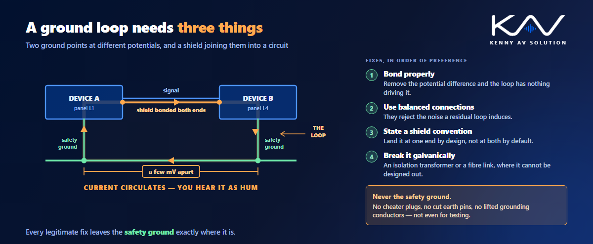
Two pieces of equipment are grounded at different points. Those points are at slightly different potentials, because they sit on different circuits, different panels, or simply a long way apart. Then you connect the two devices with a signal cable whose shield is bonded at both ends, and that shield becomes a second conductive path between them.
Current now circulates around that loop, driven by the potential difference. On audio it appears as hum at the mains frequency and its harmonics; on video it shows as bars or bands rolling through the picture. Nothing is faulty. The system is simply doing what physics requires.
Two consequences matter for drafting. First, distance and panel diversity make loops more likely, so a system spread across floors or fed from multiple panels deserves attention at design stage rather than at commissioning. Second, the cure is to remove the potential difference or break the second path — never to remove the safety path.
The one thing that must never happen
When a system hums, the fastest apparent fix is to disconnect a ground, and that instinct has killed people.
A safety ground is never lifted. Not with a three-to-two adapter, not by cutting the earth pin, not by removing the equipment grounding conductor at a receptacle, not “just for testing”. Doing so leaves the chassis of the equipment with no fault path, and the next insulation failure energises it. The hum stops; the hazard starts.
There is a legitimate control that sounds similar and is worth distinguishing clearly. Many pieces of balanced audio equipment have a ground lift switch that lifts the cable shield or the signal reference from chassis, not the safety ground. That is a normal design tool and it is safe. If you specify it, say on the drawing what it lifts, so nobody reads “ground lift” and reaches for a cheater plug.
The honest fixes, roughly in order of preference, are: bond properly so there is no meaningful potential difference in the first place; use balanced connections, which reject the noise a loop induces; terminate shields to a stated convention rather than at both ends by default, as covered in point-to-point wiring diagrams; and where a loop genuinely cannot be designed out, break it galvanically with an audio isolation transformer or an optical or fibre link. Every one of those leaves the safety ground intact.
Isolated ground: what it is and what it is not
“Isolated ground” is the most misunderstood term in AV, and the misunderstanding is dangerous.
An isolated-ground receptacle still has a full equipment grounding conductor. What is different is that this conductor is insulated and run back to the panel without being bonded to the conduit, boxes and raceway it passes through, so that noise picked up along the way does not ride into the equipment. It is a noise measure layered on top of the safety system, not a replacement for any part of it.
It emphatically does not mean a separate ground rod for the AV system. Driving an independent electrode and connecting AV equipment to it is both unsafe and, in most jurisdictions, prohibited: grounding electrodes have to be bonded together into a single system, and an isolated one creates a potential difference between AV metalwork and everything else in the building — which is the exact condition you were trying to avoid, now with a fault-current problem attached.
If isolated-ground receptacles are being used, show on the drawing which outlets they are, which panel the insulated conductor returns to, and who is providing them. This is an electrical scope item that AV has to request explicitly, the same interface discipline as everything else in AV trade coordination.
Bonding the rack and what is in it
Racks are where good intentions meet paint.
A rack is an assembly of separately finished metal parts, and powder coat is an insulator. Equipment bolted to a painted rail is not reliably bonded to the frame, and neither are the side panels, doors or shelves. Where bonding is required it has to be made deliberately: paint removed at the contact point, or paint-piercing washers used, or a dedicated bonding jumper run to a ground bar in the rack.
The practical arrangement most rooms end up with is a bonding bar mounted in each rack, with jumpers from the rack frame and from equipment that needs it, and a single conductor from that bar back to the building’s bonding infrastructure. Draw it, state the arrangement, and keep it consistent between racks so the next person finds what they expect.
Two details are worth putting on the sheet explicitly. Racks on castors or sitting on isolation pads may not be bonded through the floor at all, so the jumper is the only path. And in a multi-rack room, bonding the frames together as well as individually to the bar avoids differences between adjacent racks. This all belongs next to the rack elevation and the rack power schedule rather than in a separate universe.
Where the AV ground actually goes
The conductor leaving your rack has to end somewhere specific, and “to earth” is not an answer that anybody can install.
In structured-cabling practice the destination is defined infrastructure. TIA-607 describes a telecommunications bonding system built around a main grounding busbar at the service entrance and grounding busbars in each telecom room, tied together by a bonding backbone. Where that infrastructure exists, AV racks bond to the busbar in their room, and that room ties back to the main busbar and thence to the building’s grounding electrode system. Other regions have equivalent standards; the principle is the same everywhere.
Where no such infrastructure exists, somebody has to decide what the AV system bonds to, and it should be a decision recorded on a drawing rather than an improvisation at second fix. Show the path: rack bar, to room busbar, to backbone, to the building system. Let the electrical engineer size the conductors and confirm the method.
Because that path runs through the same pathways as everything else, it belongs on your conduit and riser drawings too — a bonding conductor needs a route, a containment allowance and somewhere to terminate, exactly like any other cable.
What belongs on the grounding and bonding drawing
Produce it as a one-line or riser in its own right. It is a small sheet that prevents large arguments.
- The bonding path, from each rack’s ground bar through to the building system, with each busbar or termination point named.
- Conductor sizes and types as specified by the electrical engineer, attributed to them rather than presented as AV’s determination.
- Which receptacles are isolated ground, if any, and which panel their insulated conductor returns to.
- Shield termination convention for the system, stated once and referenced from the cable schedule rather than restated per run.
- Where isolation transformers or optical links are used to break a loop deliberately, so nobody later removes them as redundant.
- Scope boundaries — who provides the busbar, who lands the conductor, who tests it.
- A note that safety grounds are not to be lifted, in plain words, on the sheet. It costs one line and it is the line most worth having.
Where the work is inspected, this sheet is often what an inspector wants to see, so keep it consistent with the rest of the permit set. In patient-care areas the requirements are considerably stricter and are set by the healthcare-specific parts of the electrical code, which is one of the constraints described in healthcare AV drawings — confirm those with the engineer early rather than assuming ordinary commercial practice applies.
Finally, make sure it survives into the as-built set. A bonding arrangement that exists only in the installer’s memory is an arrangement that gets undone during the first refurbishment.
Frequently asked questions
What causes a ground loop in an AV system? Two devices grounded at points with slightly different potentials, connected by a signal cable whose shield is bonded at both ends. The shield forms a second conductive path, current circulates around the loop, and it appears as hum on audio or banding on video. The equipment is not faulty.
Can you lift a ground to stop hum? Never a safety ground. Removing an equipment grounding conductor, cutting an earth pin or using a three-to-two adapter leaves equipment with no fault path and creates a genuine shock hazard. A ground lift switch on balanced audio equipment is different — it lifts the shield or signal reference, not the safety ground, and is safe to use.
Does an isolated-ground receptacle mean a separate ground? No. It still has a full equipment grounding conductor; that conductor is simply insulated and run back to the panel without bonding to the raceway along the way. It never means a separate ground rod for AV, which is unsafe and generally prohibited, because grounding electrodes must be bonded into a single system.
What should an AV grounding drawing show? The bonding path from each rack’s ground bar to the building system with every termination point named, conductor sizes as specified by the electrical engineer, any isolated-ground receptacles and their panel, the shield termination convention, any deliberate isolation devices, and clear scope boundaries for who provides and lands what.
How do you bond equipment inside a painted rack? Not by relying on the mounting screws. Powder coat is an insulator, so bonding has to be made deliberately — paint removed at the contact point, paint-piercing washers, or a dedicated jumper to a bonding bar in the rack, with one conductor from that bar to the building’s bonding infrastructure.
Need a grounding and bonding sheet in your AV set?
Kenny AV Solution produces AV drawing sets in AutoCAD for integrators, consultants and contractors worldwide — grounding and bonding risers, rack elevations with matching power and heat schedules, point-to-point and cable schedules, floor plans and RCPs, conduit and riser routing and signal flow, drawn to your standards and your title block. Send us your design intent and your engineer’s requirements and we will draw it so the intent is unambiguous on site. See our AV CAD drafting services, grab the free AV CAD Drafting Standards Checklist, or schedule a quick call — we come back with a quote and timeline within one business day. For the underlying documentation standards, AVIXA is the reference worth having on the shelf.