
Wireless microphone system drawings have to show something the rest of an AV set never does: the radio path. A cabled microphone works if the cable is connected. A wireless one works only if its signal reaches an antenna clearly, on a frequency nobody else is using, without interfering with the system in the next room. Most wireless problems — dropouts at the back of the stage, interference during the keynote, two rooms on the same channel — come from antennas and frequencies that were never drawn, only decided on the day.
Radio spectrum rules for wireless microphones differ by country and have changed in recent years; some users and bands need a licence. Check the current rules with the local regulator, and follow the manufacturer’s documentation for antennas, cabling and frequency coordination. Frequencies shown below are illustrative.
Know the band before you draw
Wireless microphones are made for different bands — commonly UHF, the 1.9 GHz band, 2.4 GHz, and infrared for classrooms that need to stay contained — and what is legal, available and crowded depends on where the building is. The band affects range, how many channels fit, how antennas are placed and whether a licence is needed. Record the band and the regulatory assumption on the drawings, so the decision is visible to whoever installs and whoever maintains the system.
Antennas are the design
Receivers in a rack, with their own small antennas behind a metal door, are the most common cause of poor range. Good practice is to place antennas where they can “see” the area the microphones are used in, and bring the signal back to the receivers on coaxial cable:
- Line of sight from the performance area to the antennas — not behind metal, video walls, columns or the audience.
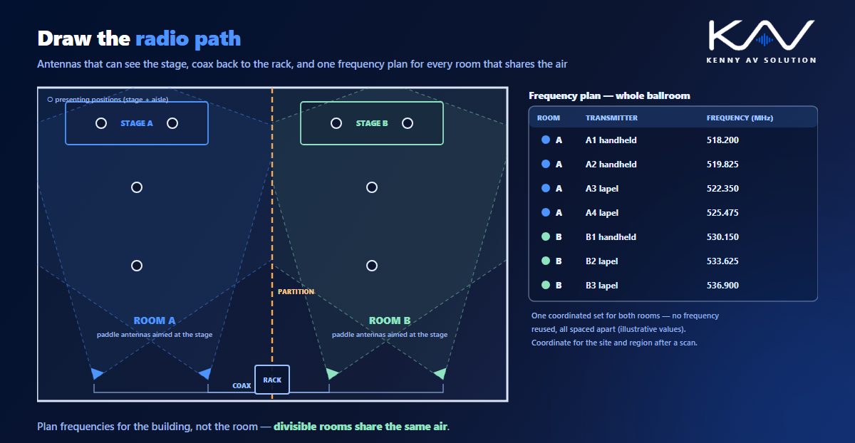
- Directional antennas aimed at the stage or presenting area for larger rooms; their coverage drawn as a wedge on the plan, the same way as a camera’s field of view.
- Two antennas per receiver system for diversity, spaced apart as the manufacturer recommends.
- Antenna distribution in the rack, so one pair of antennas feeds several receivers instead of a forest of whips.
Draw the antenna positions and mounting heights on the plans and elevations, and the coverage on the plan. Check the coverage reaches every place a presenter will stand, including the aisles if presenters walk into the audience.
Coaxial cable runs
Coax loses signal over distance, and the loss rises with frequency. Long or thin cable shortens the range the antennas were placed to achieve. Keep runs short, use the cable type the manufacturer specifies for the length, and put every run in the cable schedule with its length, so the loss can be checked against the manufacturer’s limits. Where runs are long, the manufacturer may call for in-line amplifiers or a different topology; show them.
Frequency coordination
Several transmitters in one place can interact and create interference on frequencies none of them is using, called intermodulation. That is why wireless channels are chosen as a coordinated set, usually with the manufacturer’s software, after scanning the site for what is already on the air. Put the result on the drawings as a frequency plan: every transmitter, its receiver channel and its frequency.
The plan has to cover the building, not just the room. Ballrooms that divide, adjacent meeting rooms and a theatre next to a conference centre all share the same air. A frequency plan drawn room by room, with no view of the neighbours, is how two rooms end up on the same channel. The same thinking applies to divisible rooms, where combined modes may put every microphone in one space.
Batteries, charging and storage
Wireless microphones need charging, and charging stations need a place, power and sometimes a network connection for battery monitoring. Show where the chargers live — often in the rack, a control room or a lockable cupboard — and how many there are relative to the number of transmitters, so the room is not stuck with flat batteries before the first session.
What the drawing set contains
- Plans with antenna positions, mounting heights and coverage, and the areas where microphones will be used.
- A frequency plan table covering every room that shares the same air.
- Rack elevations with receivers, antenna distribution and charging stations, as with any rack elevation.
- A signal flow from transmitter to receiver to the DSP, as part of the audio system drawings.
- Coax runs with lengths and types in the cable schedule.
In performance venues, wireless microphones often belong to the production rather than the building; the building provides antenna positions and tie lines, as described in theatre AV drawings.
Frequently asked questions
Where should wireless microphone antennas be placed? Where they have a clear line of sight to the area where the microphones are used, away from metal and obstructions, with the coverage drawn on the plan. Receivers in a rack should be fed from remote antennas on coaxial cable rather than relying on their own antennas.
What is frequency coordination for wireless microphones? Choosing a set of frequencies that do not interfere with each other or with existing signals, usually with the manufacturer’s software after a site scan. Multiple transmitters can create intermodulation products, so frequencies are chosen as a group.
Do wireless microphones need a licence? It depends on the country, the band and sometimes the user. Spectrum rules have changed in recent years in several regions, so check the current requirements with the local regulator.
What should a wireless microphone frequency plan show? Every transmitter, its receiver channel and its frequency, for every room that shares the same radio environment, so adjacent rooms and divisible spaces do not end up on the same or interfering frequencies.
Why does coax length matter for wireless microphones? Coaxial cable loses signal over distance, and more at higher frequencies. Long runs reduce the range the antennas were placed to achieve, so runs should be kept short, use the specified cable and be checked against the manufacturer’s limits.
Need wireless microphone drawings?
Kenny AV Solution drafts AV documentation for integrators, consultants and design-build teams worldwide — antenna positions and coverage, frequency plans across rooms, rack elevations with receivers and antenna distribution, coax runs in the cable schedule and audio signal flow, all drawn to your standards and your title block. See our drafting services, get an existing set checked with a drawing set review, or schedule a quick call — we come back with a quote and timeline within one business day.