
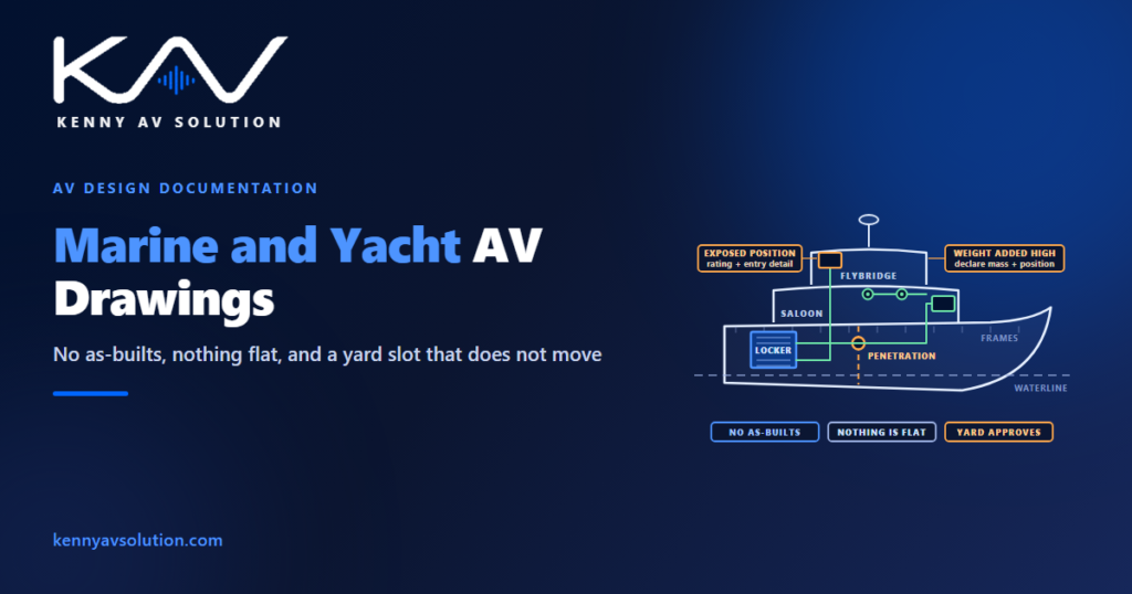
Marine AV drawings are the hardest documentation in the trade, and almost nobody writes about them. A yacht refit takes everything that makes a building project difficult — no reliable record of what exists, a fixed deadline, restricted access, other trades owning the surfaces you need — and then removes the two things every land-based drawing quietly assumes: that surfaces are flat, and that you can put a hole where you want one.
What applies to a given vessel depends on her size, flag and class, and on the yard. Structure, penetrations, weight and stability are matters for the naval architect, the yard and the surveyor — not for AV. What follows is what AV has to document and declare so those people can do their job. Confirm the specifics for your vessel before anything is cut.
There are no as-builts, and she has been changed
Start from the assumption that the drawings you are given are wrong, because on a boat they usually are.
A yacht is a one-off. The general arrangement from the yard may be decades old, and in the years since she has been sold two or three times, refitted at least once, and modified by whoever was aboard with a drill. Cable runs exist that appear on no drawing. Panels have been added. An earlier AV system was installed and half-removed.
So the survey is not a formality here, it is the entire foundation. Everything in the AV site survey applies, with more suspicion than usual and one significant addition: on a vessel, opening a panel to look behind it may itself need permission, so access has to be arranged rather than assumed.
This is also the strongest case for laser scanning anywhere in AV. Curved, irregular, one-off geometry with no trustworthy record is exactly what a point cloud is for, and a yacht is small enough that a scan is quick. Remember what it cannot tell you: it sees surfaces, not what is behind the joinery, and on a boat almost everything interesting is behind the joinery.
Nothing is flat, square or plumb
Every drawing convention you use ashore assumes orthogonal geometry. A hull has none.
The topsides curve in two directions. The deckhead follows the camber. The sole is flat only in the fore-and-aft sense, if that. Bulkheads are rarely perpendicular to anything, and a “wall” may be a curved, tapering surface that changes section along its length.
That has consequences for anything you would normally set out with a dimension from a corner. A display on a curved bulkhead needs a backing detail that follows the surface. A loudspeaker in a cambered deckhead is not firing where a plan says it is, which matters because the coverage geometry assumes a flat listening plane and a flat mounting surface — on a boat, verify by section rather than trusting the plan.
Practically: dimension from vessel references, not from room corners. Frame numbers, the centreline, a stated datum. Those exist on every vessel and they mean the same thing to the yard as they do to you. A dimension from the corner of a saloon means nothing once somebody realises the corner is a radius.
Weight is a constraint you have to declare
This is the constraint with no land-based equivalent, and it is the one integrators most often fail to document.
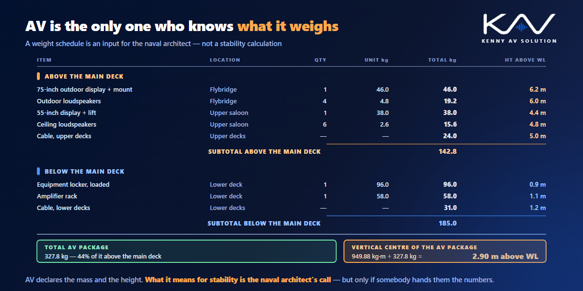
Everything added to a vessel has mass, and where that mass sits matters. Weight added high — a large display on a flybridge, an array in an upper saloon deckhead — affects stability in a way that weight in a bilge does not. Nobody expects AV to calculate that, but the naval architect cannot account for what nobody told them about.
So put the numbers on the drawing: the mass of each significant item and its position, including mounts, enclosures and the cable itself, which on a long run is not negligible. Declare it and let the people responsible for stability decide whether it matters. It is the same principle as declaring a rack heat load ashore: AV owns the number, somebody else owns the consequence.
Mounting is structural for the same reason. A bracket that would be unremarkable in a house is carrying its load through constant motion, vibration and occasional slamming. The fixing detail and what it fixes into are the yard’s to approve.
Every penetration belongs to somebody else
Ashore, drilling a partition is a decision AV can usually make. Afloat, it is never AV’s decision.
A bulkhead may be structural. It may be watertight, in which case a penetration has to be made good to a standard that preserves that. It may be a fire boundary, with its own requirements for how a cable passes through. On a vessel of any size these are matters of survey and approval, not of convenience.
The drafting consequence is that every penetration is a drawn, named item requiring approval, not an incidental part of a cable route. Show where the cable crosses a boundary, what kind of boundary it is, and whose approval is required. Where an existing route can be reused — an existing gland, a spare conduit, an established riser — use it and say so, because a reused penetration needs no new approval and is very often the difference between a change that happens and one that does not.
Treat the yard as the controlling party throughout. It is the same interface discipline as any other trade boundary, described in AV trade coordination, except that here the other trade can simply refuse.
Power and bonding are their own discipline
A vessel’s electrical system behaves in ways no building does, and this is where assumptions imported from shore work cause real damage.
Supply changes with location. Alongside she is on shore power, which may be 120V/60Hz in Florida and 230V/50Hz in the Mediterranean. At anchor she is on generator, or on inverter and batteries overnight. AV equipment that is happy on one of those may not be happy on all of them, and what is permitted to run on battery overnight is a design decision that belongs on the documentation rather than in somebody’s memory.
Bonding is not the shore-side problem either. On a vessel, connections between dissimilar metals in an electrolyte create galvanic corrosion, so marine bonding and isolation exist to manage a failure mode that simply does not occur in a building. The principles in AV grounding and bonding are useful background for the signal-reference side, but they do not transfer directly — the vessel’s bonding arrangement is the yard’s and the marine electrician’s, and AV connects to it on their terms.
What AV should document is the ordinary thing: which devices are on which supply, the load, what runs on battery, and where the equipment connects. Then let the people who own the electrical system decide.
The environment eats equipment
Salt, humidity, vibration, condensation and temperature swings are constant, and they are why marine-rated equipment exists.
Exposed positions — cockpit, flybridge, swim platform — need an appropriate ingress rating and a cable entry detailed so water cannot track in. Even inside, lockers sweat and hardware corrodes. Cable needs supporting against continuous movement rather than being run slack the way it might be in a ceiling void; a cable that is fine for ten years in a building can chafe through in a season at sea.
None of this changes how you draw, but all of it changes what the drawing has to say. Specify the rating, detail the entry, and show the support intervals. And expect service access to be the hardest part: equipment goes in lockers, under berths and behind removable panels, so show how each item comes out, not just how it goes in.
The yard slot is the whole programme
A refit happens in a window. The vessel is hauled or alongside for a defined period, other trades are working in the same spaces, and at the end of it she leaves — finished or not. There is no coming back next week.
That makes the drawings a scheduling instrument, not just a technical one. They need to exist before the slot opens, because the slot is for installing, not for deciding. Where the work is phased across more than one visit, the set has to say what is installed now, what is prepared now for later, and what remains live throughout.
And the record matters more than almost anywhere, because the next person aboard will not be you. An accurate as-built set is what stops the next refit starting from the same blank page you did — and it is the single most useful thing you can leave behind.
What a marine AV set contains
Recognisably an AV set, with additions that only make sense afloat:
- Deck plans per level, referenced to frames and the centreline rather than to room corners.
- Sections for anything on a curved or cambered surface, because a plan alone will mislead.
- A penetration schedule — every boundary crossed, its type, and whose approval is needed.
- A weight schedule, item by item with position, for the naval architect.
- Mounting details that state the substrate and the fixing, for yard approval.
- Equipment locker elevations with power, heat and — critically — removal access.
- A power schedule showing supply source, voltage and frequency range, and what runs on battery.
- A cable schedule with routes, support and environmental rating, not just endpoints.
- As-builts, marked against the same frame references.
Keep the conventions consistent with your documented AV drawing standards, because a yard reads a lot of drawings and yours should not be the confusing one. If you also do high-end houses, the discipline is closer to custom residential work than to commercial — one immovable window, concealed equipment, a demanding client — with the constraints turned up.
Frequently asked questions
Why are marine AV drawings harder than building drawings? Because a vessel has no reliable as-builts, no flat or square surfaces to dimension from, a weight budget that affects stability, penetrations that require approval from the yard or surveyor, a supply that changes between shore power, generator and battery, and a fixed yard slot after which the vessel leaves whether the work is finished or not.
What should marine AV drawings be dimensioned from? Vessel references — frame numbers, the centreline and a stated datum — rather than room corners. Those references mean the same thing to the yard as to you, whereas a dimension taken from the corner of a saloon becomes meaningless once that corner turns out to be a radius.
Does AV need to declare equipment weight on a yacht? Yes. State the mass and position of every significant item, including mounts, enclosures and cable. AV is not calculating stability, but the naval architect cannot account for weight nobody declared, and weight added high in the vessel matters far more than weight low down.
Who approves drilling through a bulkhead on a vessel? Not AV. A bulkhead may be structural, watertight or a fire boundary, so penetrations are matters for the yard, the naval architect and the surveyor depending on the vessel. Draw every penetration as a named item with its boundary type and required approval, and reuse existing routes wherever possible.
Can shore-side grounding practice be applied on a boat? No, not directly. Marine bonding exists partly to manage galvanic corrosion, a failure mode that does not occur in buildings, and the vessel’s bonding arrangement belongs to the yard and the marine electrician. Document which devices connect where and what supply they run on, and connect on their terms.
Need marine AV drawings drafted?
Kenny AV Solution produces AV drawing sets in AutoCAD for integrators, custom installers and consultants worldwide — deck plans referenced to frames, sections for curved surfaces, penetration and weight schedules, locker elevations with power, heat and removal access, cable schedules and as-builts, drawn to your standards and your title block. Send us the general arrangement, your survey notes or a scan and the equipment list, and we will produce the set your yard can actually approve. See our AV CAD drafting services, grab the free AV CAD Drafting Standards Checklist, or schedule a quick call — we come back with a quote and timeline within one business day. For the underlying documentation standards, AVIXA is the reference worth having on the shelf.