
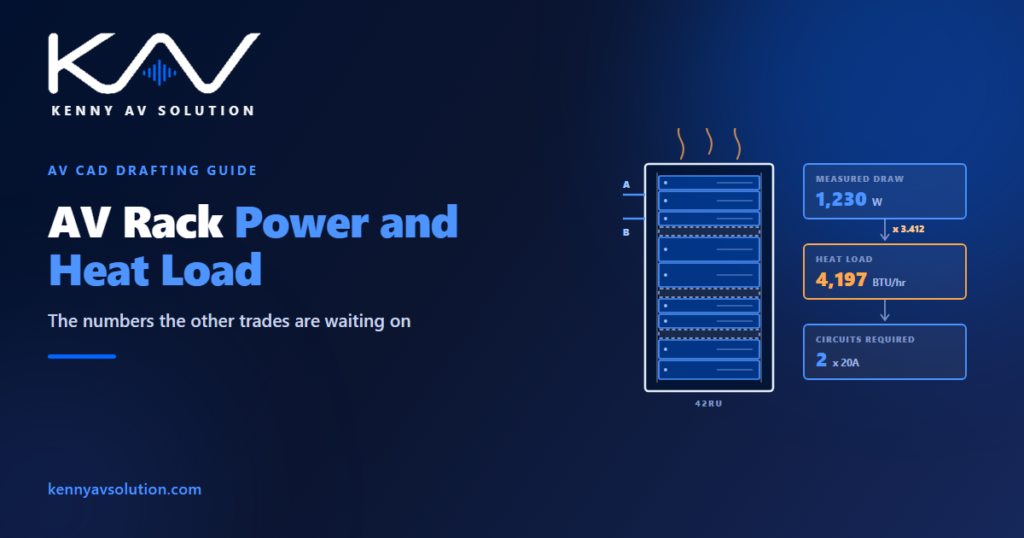
AV rack power and heat load is the number everybody needs and nobody produces. The electrical engineer wants to know how many circuits to run. The mechanical engineer wants a heat figure to size cooling against. Both ask AV, because AV is the only party who knows what is going in the rack — and AV is usually the last trade to answer, long after the electrical drawings have been issued.
The numbers below are the ones AV is responsible for declaring. Sizing the circuits, the protection and the cooling is the job of the electrical and mechanical engineers, working to the codes that apply on your project. Confirm the specifics with them and with the relevant authority.
Why the number always arrives late
Electrical design happens early. AV equipment selection happens late, often after the electrical package is out for pricing. So the rack gets a couple of general-purpose outlets on the strength of a guess, and the real requirement surfaces during installation when there is no budget left to fix it.
The way out is not to wait until the equipment list is final. Issue a provisional load at concept, state that it is provisional, and revise it as the design settles. An early figure with a stated tolerance is far more useful to the other trades than an exact figure that arrives after their drawings are frozen — the same interface discipline covered in AV trade coordination.
Nameplate draw is not real draw
Every device has a nameplate rating on the back. It is the manufacturer’s worst case: maximum load, all outputs driven, usually with margin on top. Add up the nameplate figures for a full rack and you will arrive at a number two or three times what the rack will ever actually draw.
Better data usually exists. Many manufacturers publish typical or idle consumption alongside the nameplate rating, and for anything significant it is worth asking. Where no typical figure exists, use nameplate and say so.
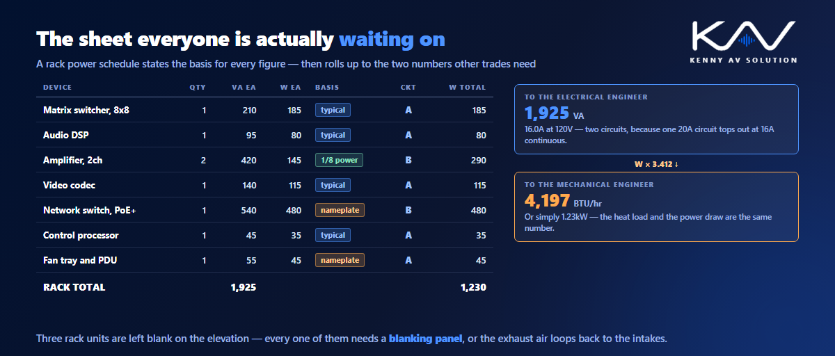
Amplifiers are the case that catches people out. An amplifier’s nameplate rating assumes continuous full output, which no amplifier driving speech or music ever sees. Real programme material has a low duty cycle, and a good deal of the energy leaves the rack down the speaker cable rather than staying in the room as heat. Manufacturers generally publish a figure at one eighth of rated power as a realistic proxy for programme use — use that where it is offered, rather than the nameplate.
Whatever you choose, put a note on the schedule stating which basis each figure came from. The next person to pick up the drawing has no way of knowing otherwise.
Watts, volt-amps and the number the electrician needs
Two different quantities get called “power” and they are used for different things.
Real power, in watts, is energy actually consumed. It is what turns into heat, so it is the number the mechanical engineer needs.
Apparent power, in volt-amps, is voltage multiplied by current. Current is what a breaker trips on and what a cable is sized for, so volt-amps are what the electrical engineer works from. Divide by the supply voltage to get amps.
For most modern AV equipment with switched-mode supplies the two figures are close, but they are not identical, and quoting a single ambiguous “power” number invites somebody to use it for the wrong purpose. State both, with the units, and label them.
From watts to heat
This conversion is the part most AV documentation skips, and it is genuinely simple: essentially all the electrical power a rack consumes ends up as heat in the room.
One watt is 3.412 BTU per hour. So a rack drawing 1,200W is putting roughly 4,100 BTU/hr into the space. If your mechanical engineer works in kilowatts, it is easier still — the heat load in kW is the same number as the power draw in kW.
The amplifier caveat applies again: power delivered to loudspeakers outside the rack room is not heat inside the rack room. For everything else, treat consumption and heat output as the same quantity and you will not be far wrong.
Give the mechanical engineer a figure in the units they use, for the space they are designing. A rack room with four racks needs one total; a lectern with a small rack inside a conference room needs its own, because that heat lands in an occupied space where somebody will notice it.
What belongs on the rack power schedule
Produce it as a sheet in its own right, alongside the rack elevation rather than buried in a note on it. Row per device, and then the totals that everybody is actually asking for:
- Device, quantity and rack position, matching the elevation and the equipment list exactly.
- Volt-amps and watts per device, with the basis stated — nameplate, typical, or manufacturer figure at one eighth power.
- Circuit assignment, so it is clear which devices sit on which feed.
- Totals per circuit and per rack, in both VA and W.
- Heat load in BTU/hr or kW, clearly labelled as such.
- Number and type of circuits required, plus the receptacle type and where they need to land.
- UPS load and required runtime, where there is one.
Keep the device names identical across the schedule, the elevation and the cable schedule. Three documents describing the same rack with three different naming conventions is how a commissioning engineer loses a day.
Circuits, diversity and headroom
A rack rarely sits on one circuit, and the split is a design decision worth drawing rather than leaving to whoever wires it.
Do not load a circuit to its rating. In the US the NEC’s continuous-load rule effectively caps a continuously operating load at 80% of the breaker rating, and other jurisdictions have equivalents — confirm which applies on your project. Beyond the code minimum, leave real spare capacity: AV racks acquire equipment throughout their life, and a rack with no headroom is a rack that gets an extension lead plugged into it in year two.
Diversity cuts the other way. Not everything runs at once, and applying a sensible diversity factor to a rack full of sources that are mostly idle produces a more honest number than a straight sum. Say what factor you applied and why, so the electrical engineer can disagree with it explicitly rather than silently.
Where circuits arrive matters as much as how many. Show the feed route and termination point on your conduit and riser drawings, and agree who is providing the final connection.
Cooling, airflow and the rack itself
Declaring the heat load is half the job. The other half is making sure the heat can actually leave the rack.
Most AV equipment breathes front to back. That only works if the front of the rack is sealed apart from the equipment itself, which means blanking panels in every unused rack unit — without them, hot exhaust air loops straight back round to the intakes and the rack slowly cooks itself on recirculated air. It is the cheapest item in the whole rack and the one most often left off the order.
A few other things belong on the drawing rather than in somebody’s head: whether the rack is vented, sealed or glass-fronted; fan tray positions and which way they move air; clearance required at front and rear, and whether the rear door can actually open where the rack is drawn; and the intake air temperature the design assumes, because a rack in a cupboard with no ventilation is not operating at room temperature.
In a sealed room running continuously, none of this is optional — the constraints described in control room AV drawings apply to any rack room that cannot be powered down.
UPS, redundancy and what it does to the drawing
Where continuity matters, the power design stops being a single number.
State which devices are on protected power and which are not, because it is almost never the whole rack. Give the UPS the load it is actually carrying and the runtime required, since runtime falls away sharply as load rises and a UPS sized on nameplate figures will be substantially oversized and expensive. Where there are dual feeds, show which devices are dual-corded and which are not — a single-corded device on an A/B rack is a single point of failure that looks resilient on paper.
And remember the UPS is itself a heat source that belongs in the total. Critical-care and continuously occupied environments make all of this explicit, which is why it features in healthcare AV drawings more than in ordinary commercial work.
Whatever the final arrangement is, it needs to survive into the as-built set. The person troubleshooting a dead rack at 7am needs to know which breaker feeds what, and the naming should follow your documented AV drawing standards.
Frequently asked questions
How do you calculate AV rack heat load? Add up the real power consumption of everything in the rack in watts, then convert: one watt is 3.412 BTU per hour, so multiply the total watts by 3.412. In kilowatts the heat load and the power draw are the same number. The exception is amplifier output delivered to loudspeakers outside the room, which does not become heat in the rack room.
Should I use nameplate ratings for rack power calculations? Only where nothing better is available. Nameplate figures are worst-case maximums and summing them across a full rack overstates the real draw considerably. Use manufacturers’ typical consumption where it is published, and for amplifiers use the figure quoted at one eighth of rated power. Always state on the schedule which basis you used.
What is the difference between VA and watts on a rack schedule? Volt-amps are apparent power and relate to current, so they are what the electrical engineer sizes circuits and cabling from. Watts are real power consumed, which is what becomes heat, so they are what the mechanical engineer needs. Quote both, labelled, rather than one ambiguous power figure.
Why do racks need blanking panels? Because AV equipment generally draws cool air in at the front and exhausts it at the rear. An open rack unit lets hot exhaust air circulate back to the intakes, so the equipment runs on progressively hotter air. Fitting blanking panels in every unused rack unit is the cheapest thermal measure available.
Who is responsible for sizing AV power and cooling? The electrical and mechanical engineers size the circuits, protection and cooling to the applicable codes. AV’s responsibility is to declare accurate loads early enough to be designed around, in the units each engineer works in, and to show the assumptions behind them.
Need rack schedules drafted properly?
Kenny AV Solution produces AV drawing sets in AutoCAD for integrators, consultants and contractors worldwide — rack elevations with matching power and heat schedules, device and cable schedules, floor plans and RCPs, conduit and riser routing and signal flow, drawn to your standards and your title block. Send your equipment list and we will build the schedule and flag what is missing. See our AV CAD drafting services, grab the free AV CAD Drafting Standards Checklist, or schedule a quick call — we come back with a quote and timeline within one business day. For the underlying documentation standards, AVIXA is the reference worth having on the shelf.