Walk into any commercial conference room — small huddle space, mid-size meeting room, large boardroom — and behind every working display, microphone, and codec there is a wiring diagram that an AV integrator drew before a single cable got pulled. When that diagram is clear, the install goes fast, the room works on day one, and service calls a year later are simple. When it’s vague, the installers guess, the room limps along, and every troubleshoot starts with a junior tech tracing cables.
This guide walks through how to actually create conference room AV wiring diagrams — what goes in them, the order you build them, and the small habits that separate amateur sketches from production-ready documentation.

What a Conference Room AV Wiring Diagram Is — and What It Isn’t
A conference room AV wiring diagram is the drawing that shows every active device in the room, every cable between them, and every signal type each cable carries. It is sometimes called a signal flow diagram, sometimes a one-line diagram, and on smaller jobs the two are merged into a single sheet.
What it is not: it is not a floor plan, not a reflected ceiling plan, and not a rack elevation. Those are different drawings in the same documentation package. The wiring diagram answers one specific question — “what connects to what, and with which cable” — and it answers it cleanly without distracting the reader with room geometry.
Step 1: Build the Device Inventory First
Before drawing a single line, list every device that will appear on the diagram. A typical mid-size conference room has 15 to 30 of them. Pull them straight from the bill of materials so the diagram and the BOM stay in sync.
For each device, capture: equipment tag (DISP-01, MIC-01, CDC-01), manufacturer and model, location (wall, ceiling, table, rack), and what signals it sends or receives. The equipment tag is the most important field — every other drawing in the set will reference these same tags.
Step 2: Group Devices into Signal Subsystems
Before laying out the diagram, sort the device list into the subsystems that make up the room:
- Video sources: laptop inputs (HDMI, USB-C), room PC, BYOD wireless presenter, document camera.
- Video distribution: matrix switcher, scaler, HDBaseT or AV-over-IP encoders and decoders.
- Displays: primary display, confidence monitor, content monitor at remote end of the room.
- Audio capture: ceiling microphone array, table mics, wireless handheld or lavalier mics.
- Audio reinforcement: DSP processor, amplifier, ceiling speakers, soundbars.
- Conferencing: codec or room computer, USB hub, far-end audio routing.
- Control: touch panel, processor, scheduling panel, occupancy sensor.
- Network and infrastructure: PoE switch, room patch panel, UPS, cable cubby connections.
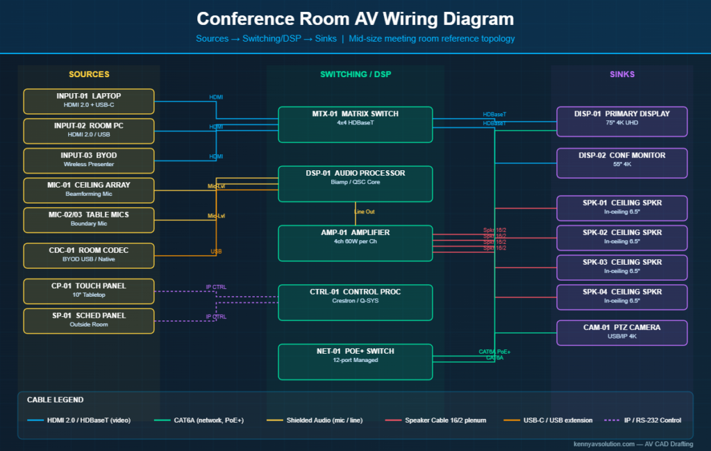
This grouping is what gives the finished diagram its readable structure. Sources go on the left, the matrix or DSP in the middle, sinks (displays, speakers, codec) on the right.
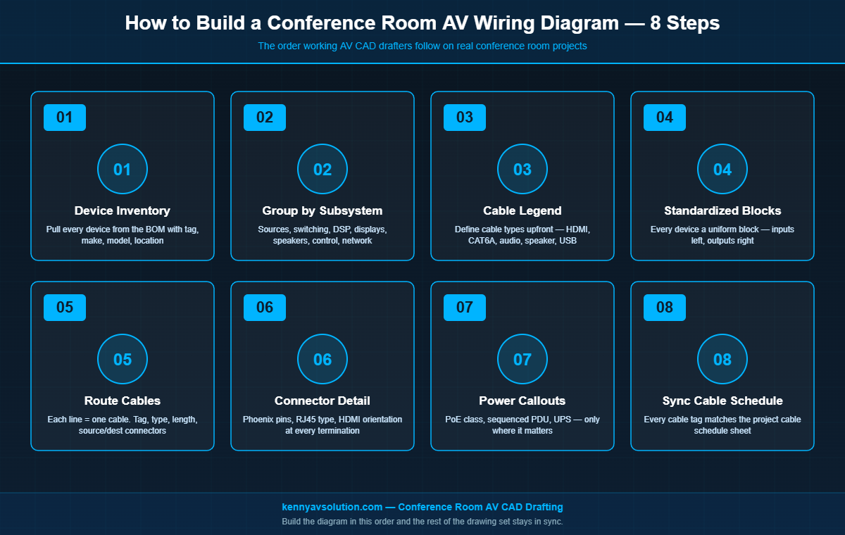
Step 3: Define the Cable Legend Up Front
Pick the cable types you’ll use and create a legend block before drawing the diagram body. A typical conference room uses 6 to 10 cable types:
- HDMI (1.4, 2.0, or 2.1 — call out which)
- USB-C (and whether it carries DP-alt mode and PD wattage)
- Cat6 or Cat6A shielded for HDBaseT, AV-over-IP, and PoE devices
- Plenum-rated speaker cable (16/2 or 14/2)
- Shielded audio cable for mic and line-level (Belden 1800F, Mogami, etc.)
- USB extension (active, fiber-extended for long runs)
- RS-232 or IP control cabling
- Power cabling (called out only where AV-rated UPS or filtered power matters)
Each cable type gets a unique line style or color in the diagram, with a small legend box in the lower-left or lower-right corner of the sheet. Consistency across every drawing in the set matters — if a green line is HDMI on the rack elevation, it has to be HDMI on the wiring diagram too.
Step 4: Draw Devices as Standardized Blocks
Every device on the diagram is a labeled block with its tag, manufacturer, and model. Inputs are shown on the left edge of the block, outputs on the right. The block is the same size and style for every device of the same class — every display looks the same, every microphone looks the same — so the eye can scan the diagram quickly.
Use a clean orthogonal block style with rounded corners or simple rectangles. Avoid pictorial icons that try to “look like” the device — they get out of date and they crowd the sheet.
Step 5: Route Cables Between Devices
This is the actual wiring. Every line on the diagram represents one physical cable. Each line gets four pieces of information:
- Cable tag: a unique identifier (C-001, C-002, etc.) that ties the line back to the cable schedule.
- Cable type: shown by line style or color, plus a short label (HDMI, CAT6A, etc.).
- Length: approximate run length, used to verify it’s within distance limits for that signal type (HDMI 4K passive runs are short; HDBaseT goes 100 m; AV-over-IP goes wherever Cat6A reaches).
- Source and destination connectors: the physical jack at each end (HDMI Type A, USB-C, RJ45, Phoenix 3-pin, etc.).
Route lines orthogonally — horizontal and vertical only, no diagonals — and avoid crossings whenever possible. Where lines must cross, use a jog or arc to make clear they are not connected.
Step 6: Show Connector Detail at Every Termination
This is the step that separates a working wiring diagram from a sketch. At every cable termination, show the physical connector and pin assignment if it matters. For a Phoenix terminal on a DSP audio input, show the three pins and what each carries (HOT, COLD, SHIELD). For an RJ45 on a network device, show that it’s a network port versus a control port. For HDMI, show whether it’s the source-side or sink-side termination.
This connector detail is what lets the installer plug things in without calling the designer. It is also what makes the diagram a real reference for service work years later.
Step 7: Add Power Cabling Where It Matters
Not every drawing shows power. But for conference rooms, you should show power where: the device is rack-mounted and gets power from a sequenced PDU, the device runs on PoE (and you need to show which PoE class), or the device needs filtered or UPS power. Standard 120V wall outlets to displays usually don’t need to appear — the EE drawings cover that.
Step 8: Cross-Reference the Cable Schedule
Every cable tag (C-001, C-002) on the wiring diagram should appear in the project’s AV cable schedule. The schedule lists each cable with its type, length, source, destination, source connector, destination connector, and pull path notes. The diagram and the schedule are two views of the same data — when one changes, both update.
Common Mistakes to Avoid
- Missing power callouts on critical devices. Displays mounted at 8 feet need power at 8 feet — call out where that power comes from.
- Ambiguous USB topology. Modern conferencing rooms route USB camera and audio through extenders and hubs. Show the exact path — host port, hub, downstream devices.
- Cable lengths that exceed distance limits. A 30-meter passive HDMI run does not work for 4K. Catch this on the diagram, not on install day.
- Inconsistent tags between drawings. If the display is DISP-01 on the floor plan but DSP-D1 on the wiring diagram, the installer loses an hour figuring it out.
- Forgotten control wiring. Most rooms have at least one RS-232 or IP control connection. Don’t leave it off the diagram because it isn’t “signal.”
Templates Speed Everything Up
Nearly every conference room you design will share 70% of its wiring topology with the last one you designed. Build a template library — huddle room, small meeting room, mid-size conference, boardroom, training room — with standard block libraries, cable legends, and title block already in place. Cloning a template and editing the device tags is dramatically faster than starting from scratch, and it forces consistency across every job your team produces.
Drawing Tools That Work for This
For most AV teams, the working tools are AutoCAD (with an AV symbol library), Visio (for quick one-line diagrams), or D-Tools / XTEN-AV (for integrated BOM-to-diagram workflows). On BIM-coordinated projects, the wiring diagram is generated as a schedule view from the Revit model. Whatever tool you pick, the rules above are the same — they’re about the diagram, not the software.
Need Conference Room Wiring Diagrams Drafted?
Kenny AV Solution drafts conference room AV wiring diagrams, signal flow diagrams, rack elevations, floor plans, and full design documentation packages for AV integrators across North America. Whether you’re a small integrator that needs overflow CAD support or a larger team outsourcing your drafting so your designers can focus on system design, we have the AV-specific workflows and template libraries to deliver fast.
If you have a conference room project on your desk and want professional documentation, contact Kenny AV Solution today for a quote.