For most of the last twenty years, AV system design lived in 2D. Floor plans, rack elevations, signal flow diagrams, RCPs — all flat drawings, all stitched together by the AV designer’s mental model of how the room actually fits together. That worked when AV scope was modest. It does not work as well when AV is integrated with structured cabling, lighting control, motorized shading, networked HVAC sensors, and a ceiling grid that has to satisfy fire protection, acoustics, and architectural intent simultaneously.
That’s where BIM for AV systems comes in. Building Information Modeling — the 3D coordinated modeling workflow that has been standard in commercial architecture and MEP engineering for over a decade — is finally crossing into AV system design in a serious way. And it’s changing how AV integrators design, document, and deliver projects.
This guide walks through what BIM means for AV, why it matters now, and what AV teams need to know to participate in BIM-coordinated projects.
What Is BIM, and What Does It Mean for AV?
BIM is not just 3D drawing. It’s a process for designing buildings using intelligent, data-rich 3D models where every component — a wall, a duct, a light fixture, a display — carries its own metadata: manufacturer, model number, dimensions, weight, power requirements, network address. Each trade contributes its own model to a shared, federated BIM environment, and clash detection software flags conflicts before they reach the field.
For AV, this means an AV designer no longer hands off a 2D floor plan with a “75-inch display, here, on this wall” annotation. They hand off a 3D AV model where the display has actual dimensions, mounting depth, viewing angle cone, cable entry point, and circuit information — and that model gets overlaid against the architect’s wall, the EE’s circuits, and the mechanical engineer’s duct runs. If the projector mount lands on a sprinkler head, BIM catches it weeks before the installer climbs the lift.
Why BIM Is Showing Up in AV Right Now
BIM has been mandated on most large commercial projects for years. What changed for AV is that owners and general contractors are now requiring the AV trade to participate at the same level as MEP. There are three drivers:
1. Owner BIM Mandates Are Getting Tighter
Federal projects (GSA, USACE), most healthcare and higher education clients, and an increasing share of corporate clients now require an LOD 350 or LOD 400 BIM model at handover. AV used to get exempted. It doesn’t anymore.
2. AV Scope Has Outgrown 2D Coordination
Modern conference rooms, classrooms, and broadcast spaces have so many ceiling-mounted devices — projectors, ceiling speakers, ceiling microphones, occupancy sensors, room scheduling panels — that a flat reflected ceiling plan can’t show whether they all physically fit. 3D modeling can.
3. Clash Detection Saves Real Money
The construction industry has decades of data showing that catching MEP clashes in BIM before construction is roughly 10x cheaper than catching them in the field. As soon as AV scope crossed a threshold of complexity, the same math started applying to AV-vs-trade coordination.
How BIM Workflows Actually Work for AV
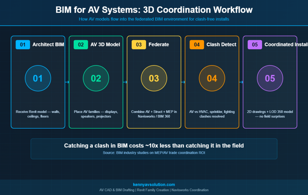
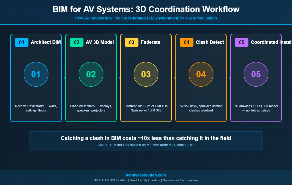
An AV BIM workflow on a real project usually follows these stages:
Stage 1: Receive the Architectural BIM Model
The AV designer imports the architect’s Revit (or sometimes ArchiCAD) model. This becomes the spatial container: walls, ceilings, floors, structural columns, doors. Without this, AV BIM modeling is just standalone 3D drawing — no coordination value.
Stage 2: Build the AV Model
The AV designer places AV equipment families into the 3D model. Most manufacturers now publish Revit families (.rfa files) for their major equipment — Crestron, Extron, Shure, QSC, Biamp, Logitech. If a family doesn’t exist, the AV team creates one from the manufacturer’s spec sheet.
Stage 3: Federate with Other Trades
The AV model gets uploaded to the project’s BIM coordination platform — usually Navisworks, BIM 360, or Autodesk Construction Cloud. The structural, mechanical, electrical, plumbing, fire protection, and AV models all live together as a federated model.
Stage 4: Clash Detection
Coordination meetings run weekly. Navisworks runs clash detection: “AV ceiling speaker SP-12 conflicts with HVAC supply diffuser at coordinate X/Y/Z.” Each clash gets reviewed, assigned to a trade, and resolved. The model gets updated, and a new clash report runs.
Stage 5: 2D Drawing Output from the BIM Model
This is where BIM for AV pays its second big dividend. Once the 3D AV model is coordinated, all the traditional AV documentation deliverables — floor plans, RCPs, rack elevations, equipment schedules — generate from the model automatically. The 2D documentation stays consistent with the 3D model because they’re the same data.
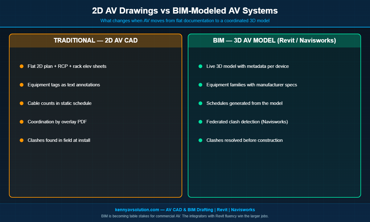
What Changes for AV CAD Drafting
When a project moves from 2D AutoCAD to BIM, AV CAD drafting changes in three concrete ways:
- Tools shift from AutoCAD to Revit (or Revit MEP). Most AV designers now keep a foot in both worlds — AutoCAD for smaller projects, Revit for BIM-mandated ones.
- Equipment schedules become live, not manual. In BIM, the equipment schedule is a view of the model. Add a display to the model, and it shows up on the schedule. Edit the model number on the schedule, and the model updates. AV cable schedules can work the same way once cables are modeled as connections between elements.
- Documentation is generated, not drawn. Instead of drafting a rack elevation by hand, the rack elevation is a 2D view of the 3D rack model. Components in the rack get placed once, and every view that shows them stays consistent.
For AV teams that have done 2D AutoCAD drafting their whole careers, this is a meaningful learning curve. Revit family creation, Navisworks clash review, BIM 360 coordination workflows — these are skills that take real time to develop.
Levels of Detail: LOD 100 to LOD 500
BIM uses a Level of Detail (LOD) framework to describe how complete a model is. AV teams should know roughly where their deliverables sit:
- LOD 100 — Conceptual: A generic placeholder. “A 75-inch display goes here, somewhere on this wall.”
- LOD 200 — Approximate Geometry: Approximate size and location. “75-inch display, mounted at 48 inches AFF, centered on the wall.”
- LOD 300 — Precise Geometry: Manufacturer-specific dimensions and exact location. This is where AV typically lives at design development.
- LOD 350 — Coordinated: Includes interfaces with adjacent components — VESA mount, wall blocking, cable entry point. This is the level required for coordination with other trades.
- LOD 400 — Fabrication: Full installation-level detail, including fasteners, conduit terminations, and cable routing. Some owners require this for handover.
- LOD 500 — As-Built: The model reflects what was actually installed. This is increasingly required as part of AV as-built documentation.
Common Challenges When AV Joins a BIM Workflow
BIM coordination on AV projects rarely goes perfectly the first time. The most common stumbles:
- Missing or inaccurate manufacturer Revit families. Manufacturer-published families are getting better, but inconsistent quality is still a real problem. AV designers regularly build their own when needed.
- AV model arrives late to coordination. If structural and MEP have already locked their model, AV has to fit around what was decided without it. Get the AV model in early.
- Cable runs not modeled. Most AV teams model devices but not cables. That works for clash detection of equipment, but conduit and pathway coordination still requires modeling cables (or at minimum modeling J-hooks, cable trays, and conduit).
- Ceiling congestion. Modern ceilings are dense. AV ceiling speakers, microphones, projectors, sensors, and room panels all compete with sprinklers, HVAC diffusers, lighting, and access panels. BIM exposes this conflict that 2D never could.
Does Every AV Project Need BIM?
No. A two-room small business AV install does not need a BIM model. The overhead — software licenses, family creation, federated coordination meetings — only pays off above a certain project complexity threshold.
The rule of thumb most integrators use: BIM is worth the investment when (a) the project owner has a BIM mandate, (b) the construction is new or major-renovation rather than a simple AV refresh, or (c) the project has more than ten ceiling-mounted AV devices and substantial coordination with other trades. Below that, traditional 2D AV floor plans and reflected ceiling plans remain the right tool.
Where 3D AV Modeling Goes from Here
The trend lines all point in the same direction. Owner BIM mandates are getting stricter, not weaker. AV scope is getting denser, not lighter. Cloud-based coordination platforms keep removing friction from federated review. And new technologies — AR field verification, automated clash detection driven by machine learning, point-cloud-to-BIM scanning of existing buildings — keep raising what BIM can do.
For AV integrators that want to win larger commercial work in the next five years, capability with BIM workflows is going to move from “differentiator” to “table stakes.” Teams that invest in Revit fluency, manufacturer family libraries, and BIM coordination experience now will be in a much better position.
Need BIM-Capable AV Drafting Support?
Kenny AV Solution provides AV CAD and BIM drafting services for integrators across North America. Whether you need a traditional 2D AV drawing set or a Revit-based 3D AV model coordinated with the rest of the project’s BIM environment, we have the workflows and template libraries to deliver. We work in AutoCAD, Revit, and Navisworks, build custom Revit families when manufacturer libraries fall short, and produce LOD 300 to LOD 400 AV models for coordination and fabrication.
If your team is being asked to participate in a BIM-coordinated project for the first time — or you’re an integrator looking to add BIM capability without building it in-house — contact Kenny AV Solution today to scope the work.