
Walk onto any commercial AV job site mid-build and you’ll see the same scene: a low-voltage installer staring at a stack of drawings, trying to figure out which conduit a fiber run is supposed to go through, and an electrical contractor pointing at a riser sleeve they thought was already pulled. Almost every one of these conversations comes back to the same two documents — the AV conduit drawing and the AV riser diagram.
These two documents are easy to confuse. Both deal with cable pathways. Both are unglamorous. Both get skipped on tight-budget projects. And on every project where they get skipped, somebody ends up paying for it later — usually with extra labor, change orders, or a coring crew.
This guide breaks down what AV conduit and riser diagrams actually are, what they show, and why every system integrator should treat them as core deliverables — not afterthoughts.
What Is an AV Riser Diagram?
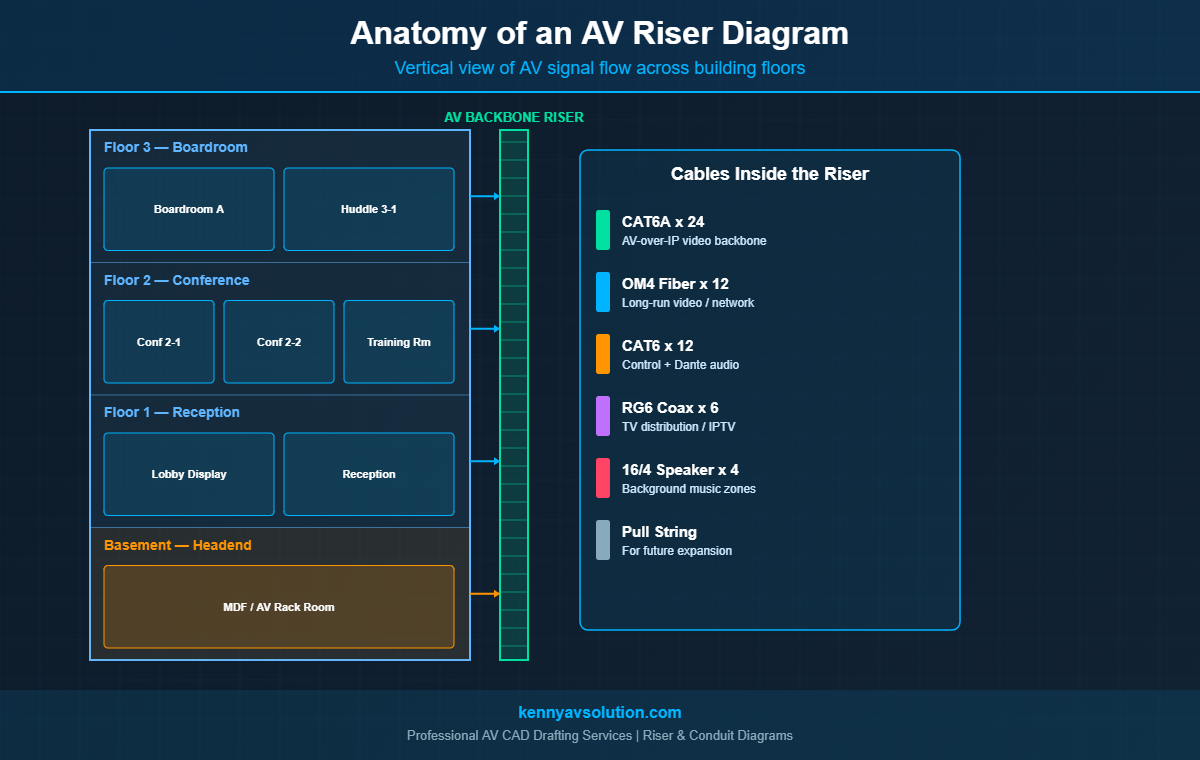
An AV riser diagram is a vertical, building-wide schematic that shows how AV signals travel between floors and major zones. It’s not a floor plan and it’s not a signal flow diagram — it sits somewhere in between. The riser tells you, at a glance, how the AV backbone connects head-end equipment in a basement or telecom room to displays, speakers, and control points on every floor above.
Riser diagrams are common in commercial construction documents. The electrical engineer has a power riser. The IT consultant has a structured cabling riser. The AV designer should produce an AV riser to match — showing fiber backbones, IP video distribution, audio over IP, control runs, and any other building-wide AV infrastructure.
What an AV Riser Diagram Typically Shows
- Each floor of the building, stacked vertically
- The AV head-end (rack room, IDF, or MDF) with main equipment labels
- Vertical riser sleeves or pathways connecting floors
- Cable types and quantities in each riser
- Equipment terminations on each floor (switches, displays, codecs)
- Cross-references to floor plan sheets for horizontal pathways
What Is an AV Conduit Drawing?
An AV conduit drawing — sometimes called a conduit pathway plan — is a horizontal, floor-by-floor view of the conduit infrastructure that AV cabling runs through. It documents conduit IDs, sizes, routes, and the cables pulled inside each one.
Conduit drawings live on the AV documentation set, but they’re often produced in close coordination with the electrical contractor. In commercial construction, the EC typically installs the conduit and pull boxes during rough-in, and the AV integrator pulls cable later. Without a clear conduit drawing, the EC has no way to know what size conduit to install, where to put pull boxes, or where to leave service loops.
What an AV Conduit Drawing Typically Shows
- Each conduit run with a unique ID (e.g.,
C-101,C-102) - Source and destination of each conduit (room-to-room or room-to-rack)
- Conduit size and material (e.g., 2″ EMT, 1″ PVC)
- Cables to be pulled inside, with quantities
- Estimated conduit fill percentage
- J-box and pull box locations
- Stub-up and stub-down points
Riser vs Conduit Diagram — What’s the Difference?
The two diagrams answer different questions. The riser asks: how does AV signal flow vertically through the building? The conduit drawing asks: what physical pathways does the cable travel through on each floor?
Think of it this way: the riser is the elevator. The conduit drawing is the hallway. Both are needed to get from one room on Floor 3 to a piece of equipment in the basement rack room. Most projects need both, even if the project is small enough that one of them fits onto a single sheet.
What Goes On an AV Riser Diagram
A complete AV riser diagram should give a project manager a one-glance answer to “where does the AV backbone go in this building?” Here’s what to include:
Floor Stack and Building Zones
Show every floor where AV equipment lives, plus the head-end. If the building has multiple wings or zones with separate IDFs, show those too. Use clear labels like Floor 3 — Boardroom or Basement — MDF.
Equipment Locations on Each Floor
Boxes for each major AV device: codecs, displays, IDF switches, audio DSPs, IP cameras. Use the same equipment tags (DSP-01, VID-SW-02) that appear on your signal flow diagrams. Consistency between sheets is non-negotiable.
Vertical Backbone Cables
Show the cable bundles inside each riser sleeve — for example, “12-strand OM4 fiber, 24× CAT6A, 4× CAT6 control.” This tells the integrator exactly what to pull and helps the EC size the riser sleeve correctly.
Termination Points
Where each riser cable lands — usually a patch panel in an IDF or a piece of equipment in a rack. Show these as labeled connection points.
Future-Proofing Notes
Many AV risers include a pull string and spare conduit capacity for future expansion. Document these. Five years from now, somebody will be glad you did.
What Goes On an AV Conduit Drawing
The conduit drawing operates on the floor plan layer. Here’s what every conduit pathway sheet should capture:
Conduit ID and Size
Every conduit gets a unique ID — a common scheme is C-101, C-102, etc., where the first digit indicates the floor. Each conduit’s nominal size (1″, 2″, 4″) is called out either on the conduit itself or in a schedule.
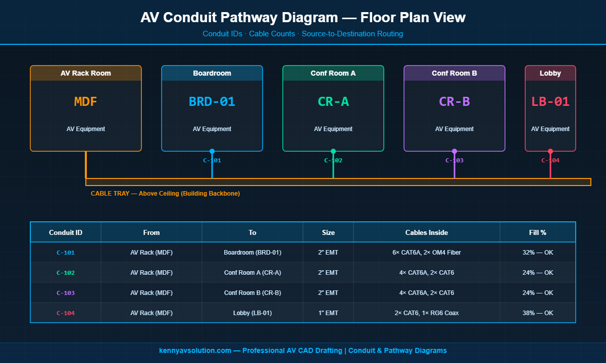
Source and Destination
From which room or J-box, to which room or J-box. This needs to match the room labels on the floor plan and the equipment tags on the rack elevation. See our floor plans vs reflected ceiling plans guide for how this connects to the broader documentation set.
Cables Inside Each Conduit
List every cable that will pull through, with quantities and types. This is what the EC uses to size the conduit and what the AV integrator uses to plan the pull.
Conduit Fill Calculations
Per NEC Chapter 9, conduits have maximum fill percentages (40% for three or more conductors). Showing the calculated fill on the drawing prevents the “we need to add another cable” problem from becoming a “we need to add another conduit” problem.
Pull Box and J-Box Locations
Long runs and bends require intermediate pull boxes. Document them. The EC needs this to know where to install pull box hardware during rough-in.
Why System Integrators Need Both Diagrams
A few reasons these two documents are worth the design hours:
Coordination With Other Trades
The electrical contractor, low-voltage contractor, and general contractor all touch AV pathways at some point. Without clear conduit and riser drawings, they’re guessing — and guesses get expensive when concrete is poured.
Accurate Procurement and Bids
An integrator bidding a job without a conduit drawing has to estimate cable quantities and conduit sizes. With a proper drawing, the bid is a count, not a guess. Material orders are accurate, and there’s a defensible record of scope.
Code Compliance
NEC, NFPA 70, and local building codes have specific rules for low-voltage cable in conduit, plenum spaces, and risers. Documented conduit fill calculations and routing keep you on the right side of inspectors.
Long-Term Serviceability
Five years from now, when somebody needs to add a display in the boardroom, the conduit drawing tells them whether there’s spare capacity in the existing conduit or whether new pathway is needed. Without it, they’re pulling ceiling tiles to find out.
Best Practices for AV Conduit and Riser Diagrams
Coordinate Early With the Electrical Engineer
Conduit installation usually happens during electrical rough-in, weeks or months before AV install. The AV designer needs to deliver conduit drawings early enough for the EE to coordinate with the EC. Late conduit drawings mean change orders.
Use Standardized Symbols
Following the AVIXA AV drawing symbols standard for J-boxes, conduit endpoints, and equipment makes your drawings instantly readable to anyone in the AV trade.
Tie Everything to a Cable Schedule
Conduit drawings show pathways. The cable schedule shows individual cable runs. The two should reference each other — every cable in the schedule should be pulled through a documented conduit. See our guide to AV cable schedules for how to keep them in sync.
Update During Construction
Conduit and riser drawings almost always change during install. Maintain a redline copy on site and roll the changes into as-built drawings at project closeout. The next service tech will thank you.
How They Fit Into the Documentation Package
Conduit and riser diagrams are two pieces of a complete AV documentation set that also includes signal flow diagrams, floor plans, rack elevations, equipment schedules, and cable schedules. None of these documents stand alone — they reference and depend on each other. For a complete breakdown, see our overview of the complete AV design documentation package.
Let Kenny AV Solution Build Your Conduit and Riser Drawings
Producing accurate AV conduit and riser drawings takes time, coordination with other trades, and real-world install knowledge. If your team is busy designing systems and managing installations, outsourcing the drafting work can free up significant capacity without compromising quality.
At Kenny AV Solution, we deliver complete AV documentation packages — including conduit drawings, riser diagrams, signal flow diagrams, rack elevations, cable schedules, and as-builts — fully cross-referenced and ready to coordinate with your electrical and structural teams. Every drawing we produce is install-ready and AVIXA-aligned.
Need help with conduit and riser documentation on your next project? Contact Kenny AV Solution today and let’s talk about your scope.