When you’re deep in an AV design project, two drawing types come up constantly: floor plans and reflected ceiling plans (RCPs). These documents look similar at first glance, but they serve very different purposes — and confusing them can lead to costly installation errors, missed equipment placements, and unhappy clients.
This guide breaks down exactly what each drawing type covers, how they work together in AV design, and what you need to include in each to deliver professional, bid-ready documentation.

What Is an AV Floor Plan?
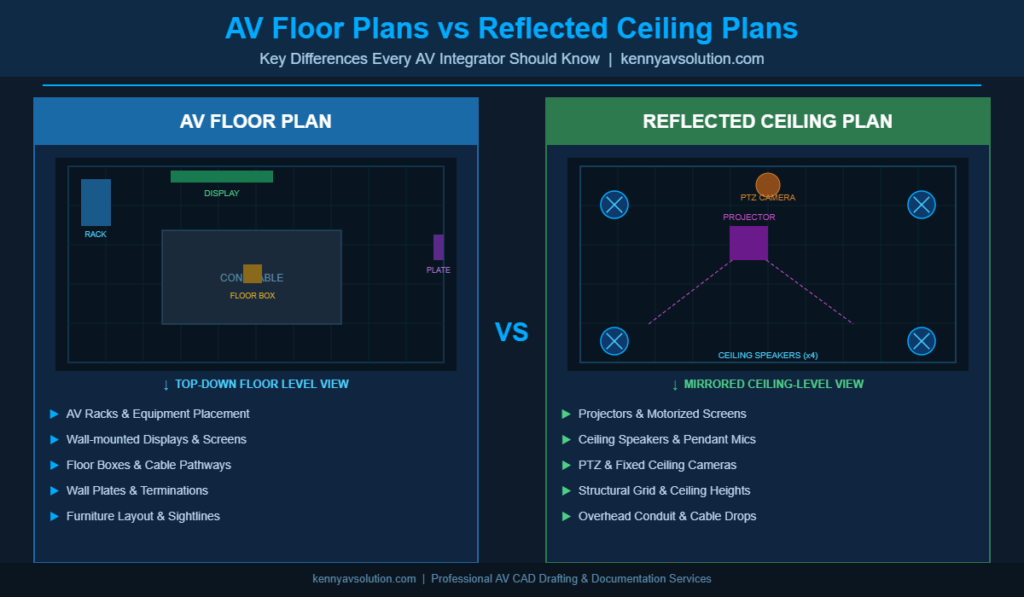
An AV floor plan is a top-down view of a room or building showing how AV equipment, furniture, and infrastructure are laid out at the floor level. Think of it as looking straight down through the ceiling — you’re seeing where things sit and how the space functions from ground level.
In AV design, floor plans typically include:
- Equipment placement: Racks, displays, podiums, control panels, and furniture
- Cable pathways: Conduit runs, floor boxes, cable trays, and wireways
- Wall-mounted equipment: Touchscreens, keypads, termination plates, and data drops
- User interaction zones: Presenter areas, audience seating, and sightlines
- Dimensions and room layout: Accurate measurements that coordinate with architectural drawings
Floor plans are essential for communicating where equipment will be physically located — to clients, general contractors, and installation crews. They’re also the starting point for any AV design. Before you worry about what’s on the ceiling, you need to know what’s on the floor.
What Is a Reflected Ceiling Plan?
A reflected ceiling plan (RCP) is a view of the ceiling as if you placed a mirror on the floor and looked down at it. This “reflection” convention gives you an accurate top-down representation of everything installed overhead, while maintaining the same orientation as the floor plan for easy cross-referencing.
In AV design, RCPs typically show:
- Projectors and displays: Ceiling-mounted projectors, motorized screens, and video walls
- Speakers: Ceiling speakers, pendant speakers, and distributed audio clusters
- Lighting: Architectural lighting that interacts with display visibility and presentation zones
- Structural elements: Beams, soffits, and drop ceiling grid layouts
- Cable drops and raceways: Overhead conduit routing and ceiling penetrations
- PTZ cameras: Ceiling-mounted cameras for videoconferencing systems
The RCP is where AV design gets technical. Ceiling-mounted equipment requires coordination with structural engineers, lighting designers, MEP trades, and general contractors — making accurate, detailed RCPs a non-negotiable part of your documentation package.
Why Both Drawings Are Required in Professional AV Design
Some AV integrators try to get by with a single combined drawing. That’s a mistake for several reasons.
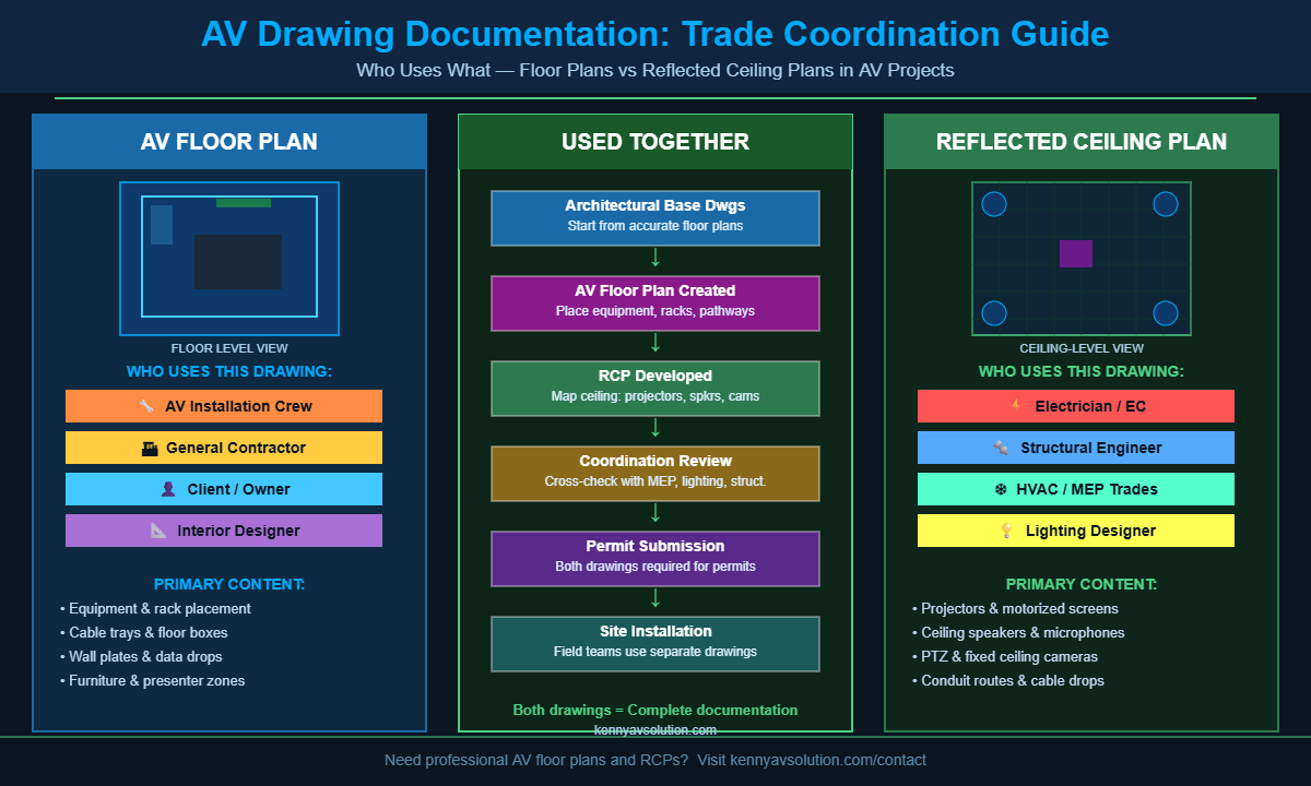
Clarity and Trade Coordination
Different trades work from different drawings. Your electrician needs to know what’s on the ceiling — circuit drops, conduit routes, and power requirements. Your low-voltage crew needs the floor plan to know where racks, wall plates, and floor boxes go. Combining everything into one drawing creates a cluttered mess that no one can read on a job site.
Providing separate, clean floor plans and RCPs keeps information organized and dramatically reduces installation errors caused by misread drawings.
Code Compliance and Permit Submissions
Many jurisdictions require separate floor plans and RCPs as part of permit documentation. Building departments expect to see ceiling-level work called out on an RCP, not buried in a floor plan. If your documentation doesn’t match the standard format, you could face permit delays that push back the entire project schedule.
Client Communication and Change Orders
Clean, professional drawings help clients visualize the finished space. When a client says “I thought the projector would be centered over the table,” being able to point to the approved RCP protects you legally and professionally. Separate drawings reduce ambiguity and create a clearer paper trail for change orders.
AV Floor Plans vs RCPs: Key Differences at a Glance
| Feature | AV Floor Plan | Reflected Ceiling Plan |
|---|---|---|
| View | Looking down at floor level | Looking up at ceiling (mirrored) |
| AV Equipment Shown | Racks, floor boxes, wall plates, displays | Projectors, ceiling speakers, PTZ cameras |
| Primary Users | Installation crew, GC, owner | Electrician, structural, MEP trades |
| Coordinates With | Furniture, millwork, floor finishes | HVAC, lighting, fire suppression |
| Required For | Equipment layout approval | Permit submissions, overhead rough-in |
How AV Floor Plans and RCPs Work Together
These two drawings are meant to be read side-by-side. A projector on the RCP needs to align with the screen mounting detail on the floor plan. A ceiling-drop microphone on the RCP needs to match the DSP input callout on your signal flow diagram.
Cross-referencing between drawings is where professional AV design documentation proves its value. When every drawing aligns — floor plans, RCPs, single-line diagrams, and cable schedules — you eliminate field guesswork and significantly reduce the risk of costly rework.
Elevation Views Add a Third Dimension
For complex installations, floor plans and RCPs are supplemented with elevation drawings. These side-view drawings show equipment mounting heights, rack layouts, and wall-mounted panel details that can’t be fully communicated from a top-down perspective.
Together, floor plans + RCPs + elevations form the core spatial documentation set for any professional AV project. This full package becomes even more powerful when paired with detailed signal flow diagrams and cable schedules.
What AV Integrators Often Get Wrong
Here are the most common floor plan and RCP mistakes that cause real problems on job sites:
- Not coordinating with base architectural drawings: AV drawings should always be overlaid on or traced from current architectural drawings. Working from outdated base drawings causes equipment to end up in the wrong location.
- Omitting ceiling heights: A ceiling speaker that works acoustically at 9 feet performs very differently at 14 feet. RCPs should clearly note ceiling heights throughout the space.
- Ignoring HVAC and lighting conflicts: Ceiling-mounted speakers and projectors need to avoid supply air diffusers, return air grilles, and pendant light fixtures. Failing to coordinate these means expensive field relocations.
- Using non-standard symbols: If your drawings use symbols field crews don’t recognize, misreads happen. Use AVIXA-standard AV symbols consistently across all drawings.
- Combining too much on one sheet: If you’re showing floor equipment, ceiling equipment, conduit runs, and furniture all on a single sheet, you’ve created a document no one can read in the field. Layer your drawings properly.
When to Outsource Your AV CAD Drawings
Creating professional floor plans and reflected ceiling plans takes time, skill, and the right software. Many AV integrators — especially smaller shops — don’t have a dedicated CAD technician on staff. That’s where outsourcing makes sense.
At Kenny AV Solution, we specialize in creating precise, professional AV floor plans and reflected ceiling plans that are ready for permit submission, client approval, and installation. Our team works with AutoCAD and other industry-standard tools to produce documentation that accurately reflects your design intent — delivered on the timeline your projects demand.
Whether you need a single room layout or a full documentation package for a multi-room project, we deliver fast turnaround without sacrificing quality. Contact us today to discuss your project requirements and get a free quote on AV CAD drafting services.
Conclusion
AV floor plans and reflected ceiling plans each serve a distinct, critical purpose in the design and installation process. Floor plans ground your equipment layout in the physical space. RCPs map the ceiling infrastructure that makes modern AV systems function. Together, they form the foundation of any professional AV design documentation package.
Getting these drawings right — with accurate dimensions, correct symbols, and proper trade coordination — is the difference between a smooth installation and a frustrating field rework. If your team is stretched thin or you need drawings that meet professional standards, Kenny AV Solution is here to help.
Reach out to our team and let’s talk about what we can do for your next project.