
If you work in the AV integration industry, you have probably seen signal flow diagrams on project documentation packages. But do you truly understand how to read them, create them, and use them to streamline your installations? A well-crafted AV signal flow diagram is one of the most powerful tools in a system designer toolkit.
In this comprehensive guide, we will walk through what AV signal flow diagrams are, why they are critical for successful AV projects, and how to create professional ones that your installation teams and clients will thank you for.
What Is an AV Signal Flow Diagram?
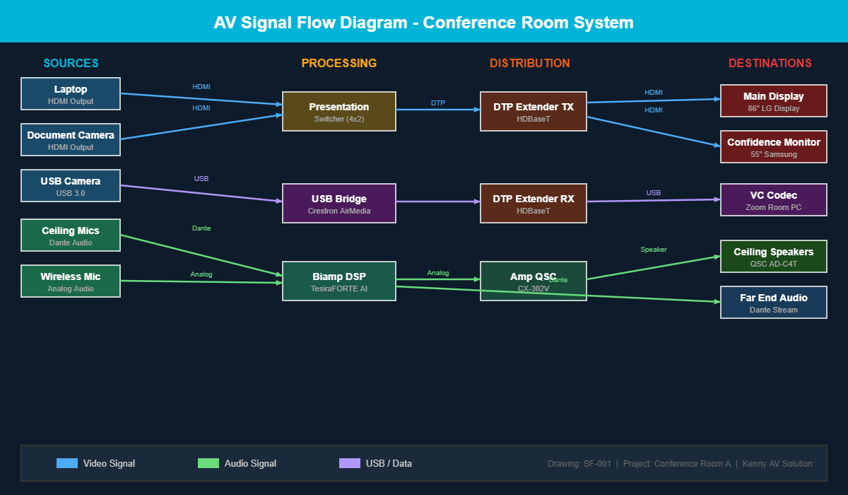
An AV signal flow diagram is a visual representation of how audio, video, and control signals travel through an AV system from source to destination. Unlike a simple block diagram that just shows equipment connections, a signal flow diagram traces the actual path each signal takes, showing every processing step, routing decision, and distribution point along the way.
Think of it as a roadmap for your AV signals. Just as a highway map shows how traffic moves between cities, a signal flow diagram shows how a video signal travels from a laptop input through a switcher, across a matrix, over an extender, and finally to a display on the wall.
Why Signal Flow Diagrams Matter for AV Projects
Many AV integrators skip signal flow diagrams and rely on simple connection lists or verbal instructions. This approach might work for a basic single-room setup, but it falls apart quickly on larger projects. Here is why signal flow diagrams are worth the investment:
1. They Eliminate Guesswork During Installation
When your field technicians can see exactly how signals route through the system, they spend less time figuring out connections and more time actually installing equipment. A clear signal flow diagram answers questions before they are asked, reducing phone calls back to the engineering team and keeping projects on schedule.
2. They Catch Design Errors Early
Drawing out the complete signal path forces the designer to think through every connection point. Missing a format conversion, forgetting a signal distribution amplifier, or overlooking a control pathway becomes obvious on a diagram long before it becomes a problem on site. Finding these issues during the design phase costs almost nothing compared to discovering them during commissioning.
3. They Simplify Troubleshooting
When something stops working six months after installation, the signal flow diagram becomes the first reference document a service technician reaches for. They can trace the signal path from source to destination and quickly identify where the break might be occurring. Without this diagram, troubleshooting becomes a time-consuming process of tracing cables and testing connections blindly.
4. They Improve Client Communication
Not every client understands AV technology, but most can follow a well-designed signal flow diagram. It gives them a clear picture of how their system works, making it easier to discuss upgrades, explain limitations, and set realistic expectations about system capabilities.
Key Elements of a Professional AV Signal Flow Diagram
A signal flow diagram is only useful if it contains the right information presented clearly. Here are the essential elements every professional AV signal flow diagram should include:
- Signal sources clearly labeled with device types and locations such as laptops, cameras, microphones, and media players
- Signal destinations including displays, speakers, recording devices, and streaming endpoints
- Processing equipment like DSPs, video scalers, audio mixers, and codec units
- Switching and routing devices including matrix switchers, presentation switchers, and AV over IP endpoints
- Signal types differentiated by line style or color for audio, video, control, and network signals
- Connection standards labeled on each path such as HDMI, HDBaseT, Dante, USB, and RS-232
- Signal direction arrows showing which way signals travel through the system
- Room or zone boundaries indicating where signals cross between different physical spaces
Common Types of AV Signal Flow Diagrams
Depending on the project complexity and audience, you might create different types of signal flow diagrams:
System-Level Signal Flow
This is the big picture view showing how signals move between major system components. It is ideal for client presentations and high-level design reviews. Equipment is shown as labeled blocks without internal detail.
Detailed Signal Flow
This diagram shows every input, output, and processing stage in detail. It includes specific port assignments, signal formats at each stage, and any format conversions that occur. This is the version your installation team needs.
Control Signal Flow
A dedicated diagram showing how control signals route through the system. This covers RS-232 connections, IP-based control paths, infrared routing, and relay closures. Control flow is often overlooked but is essential for programming and troubleshooting automated systems.
Best Practices for Creating AV Signal Flow Diagrams
After years of creating signal flow diagrams for AV projects of all sizes, here are the practices that consistently produce the best results:
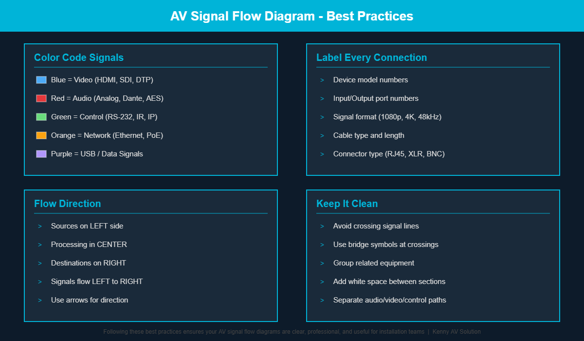
Use Consistent Color Coding
Assign specific colors to different signal types and stick with them across all project documents. A common convention uses blue for video, red for audio, green for control, and orange for network signals. This makes diagrams instantly readable even for people seeing them for the first time.
Flow Left to Right
Arrange your diagram so signals generally flow from left to right, with sources on the left side and destinations on the right. This follows natural reading patterns and makes the diagram intuitive to follow.
Label Everything
Every device, every signal path, and every connection point should be labeled. Include model numbers for equipment and specify signal formats on each connection. The few extra minutes spent labeling save hours of confusion later.
Keep It Clean
Avoid crossing signal lines wherever possible. If lines must cross, use a bridge or hop symbol to make it clear that the signals are not connected at that point. White space is your friend. A cluttered diagram defeats the purpose of creating one in the first place.
How Kenny AV Solution Can Help with Your Signal Flow Diagrams
Creating professional signal flow diagrams requires both AV system knowledge and CAD drafting expertise. At Kenny AV Solution, we combine deep understanding of AV technology with professional drafting skills to deliver signal flow diagrams that are accurate, clear, and ready for installation.
Our AV CAD drafting services include signal flow diagrams as part of comprehensive design documentation packages that also cover rack elevation drawings, cable schedules, floor plans, and reflected ceiling plans. We work with AutoCAD, Visio, D-Tools, and other industry-standard tools to match your existing workflow.
Get Professional AV Signal Flow Diagrams for Your Next Project
Whether you are designing a single huddle room or a multi-building corporate campus, having clear and accurate signal flow diagrams will save you time, reduce installation errors, and impress your clients with thorough documentation.
Contact Kenny AV Solution today to discuss your signal flow diagram needs or to learn more about our complete AV CAD drafting services.