If you have ever worked on a commercial AV project, you know that one of the most critical deliverables is the rack elevation drawing. Whether you are an AV integrator, a system designer, or a project manager overseeing an installation, understanding rack elevation drawings can mean the difference between a smooth installation and costly on-site rework.
In this guide, we break down everything you need to know about AV rack elevation drawings, why they matter, what they include, and how professional CAD drafting ensures accuracy from design to installation.
What Is an AV Rack Elevation Drawing?
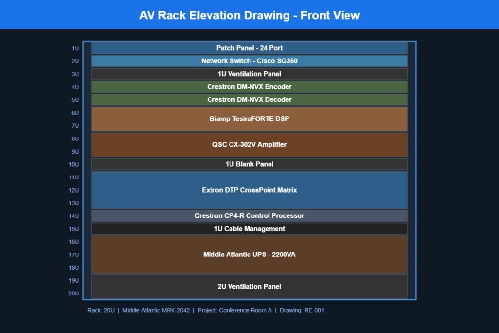
An AV rack elevation drawing is a detailed, scaled diagram that shows exactly how audio visual equipment will be arranged inside a standard equipment rack. Think of it as a blueprint for your AV rack. It shows every component, its position measured in rack units (RU), the spacing between devices, and how everything fits together vertically within the rack enclosure.
These drawings are typically created in AutoCAD, Visio, or specialized AV design tools like D-Tools and are delivered as part of a complete AV design documentation package.

Why Are Rack Elevation Drawings Important for AV Projects?
Without a proper rack elevation drawing, installation teams are left guessing. That leads to wasted time, incorrect equipment placement, and potential overheating issues. Here is why every AV project needs them:
1. Accurate Equipment Placement
Every piece of AV gear, from amplifiers and DSPs to video switchers and network switches, occupies a specific number of rack units. A rack elevation drawing maps out exactly where each device sits, ensuring nothing overlaps or exceeds the available rack space.
2. Proper Ventilation and Heat Management
Heat is one of the biggest enemies of AV equipment reliability. Rack elevation drawings help designers plan for adequate ventilation panels, blank filler panels, and spacing between heat-generating devices. Getting this wrong can shorten equipment lifespan and cause intermittent failures that are expensive to troubleshoot.
3. Simplified Installation
When technicians arrive on site with a clear rack elevation drawing in hand, they know exactly what goes where. This reduces installation time, minimizes errors, and keeps the project on schedule. For large-scale deployments with multiple identical rooms, standardized rack drawings become even more valuable.
4. Better Client Communication
Rack elevation drawings give clients a visual understanding of how their AV system will be organized. This transparency builds trust and makes it easier to get approvals before equipment is ordered and installed.
5. Streamlined Maintenance and Troubleshooting
After installation, rack elevation drawings serve as ongoing reference documents. When a technician needs to swap out a faulty device or add new equipment months later, the drawing tells them exactly what is in the rack and where it is located.
What Should a Professional AV Rack Elevation Drawing Include?
A well-prepared rack elevation drawing goes beyond just showing boxes in a rack. Here are the key elements that should be included:
- Equipment names and model numbers for every device in the rack
- Rack unit positions (RU numbering from top to bottom or bottom to top)
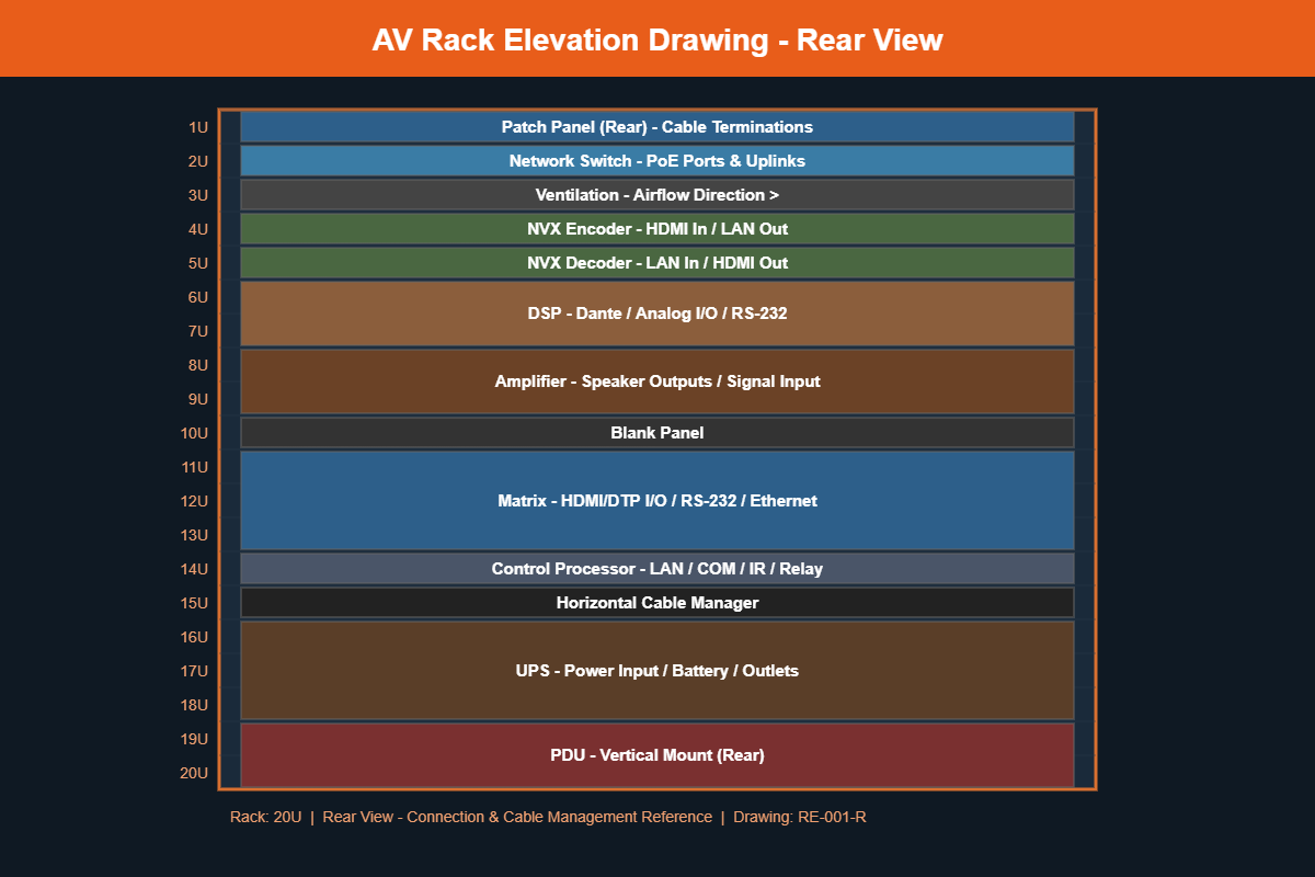
- Front and rear views showing both the faceplate side and the connection side
- Ventilation panels and blank fillers clearly marked
- Power distribution units (PDUs) and their mounting positions
- Cable management accessories such as horizontal and vertical cable managers
- Rack dimensions and total RU count (commonly 42RU, 22RU, or 12RU)
- Equipment weight for structural planning when needed
Common Mistakes in AV Rack Elevation Drawings
Even experienced AV designers sometimes make errors in their rack drawings. Here are the most common pitfalls to watch out for:
- Forgetting rear-mounted equipment like power strips and small network switches
- Not accounting for ventilation space between heat-generating devices
- Using incorrect RU sizes for equipment, leading to space conflicts during installation
- Missing cable management which causes messy racks and difficult troubleshooting
- Not including both front and rear views which leaves installation teams guessing about connections
How Professional AV CAD Drafting Services Can Help
Creating accurate rack elevation drawings takes time, attention to detail, and expertise in both AV systems and CAD software. Many AV integrators choose to outsource this work to specialized AV CAD drafting services for several reasons:
- Faster turnaround so your design team can focus on system engineering and client relationships
- Consistent quality across all project documentation
- Scalability for large projects with dozens of racks across multiple rooms or buildings
- Cost savings compared to hiring full-time in-house CAD drafters
At Kenny AV Solution, we specialize in creating professional AV rack elevation drawings along with complete AV design documentation packages including signal flow diagrams, cable schedules, floor plans, and reflected ceiling plans. Our team works with AutoCAD, Visio, D-Tools, and other industry-standard platforms to deliver drawings that meet AVIXA standards.
Ready to Get Your AV Rack Drawings Done Right?
Whether you need rack elevations for a single conference room or a full corporate campus, our AV CAD drafting team is ready to help. We deliver accurate, professional drawings that keep your projects on track and your clients happy.
Contact us today to discuss your next AV project or request a free consultation on your CAD drafting needs.