
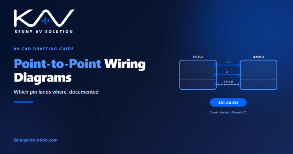
Point-to-point wiring diagrams are the sheets that tell an installer exactly which pin lands where. Where a signal-flow drawing shows how the system thinks, a point-to-point wiring diagram shows how it is actually wired — connector by connector, pin by pin. This guide covers what belongs on one, when your project needs them, how they differ from the other diagram types in an AV set, and the mistakes that turn a useful sheet into a liability.
What is a point-to-point wiring diagram?
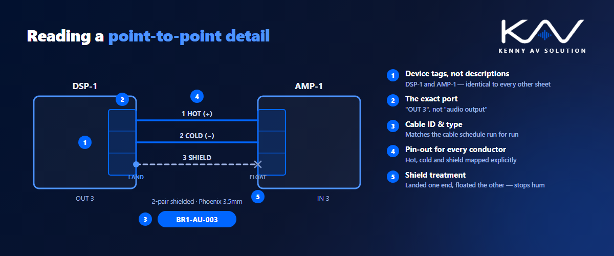
A point-to-point wiring diagram documents the physical connection between two specific devices. It names both endpoints, the exact port or terminal on each, the cable and connector type, and — where it matters — the pin-out on each end. Nothing is implied. An installer should be able to build the connection without knowing anything about the wider system design.
That is the key difference from the other diagrams in an AV set. A signal-flow diagram shows the logical path from source to display. An AV single-line diagram compresses that path into one line per connection for a fast overview. A point-to-point wiring diagram zooms all the way in on a single link and documents it completely.
What belongs on a point-to-point wiring diagram
A complete point-to-point sheet carries the detail an installer would otherwise have to guess at:
- Both device tags — matching the tags used everywhere else in the set, exactly.
- The specific port on each end — not “DSP output” but “DSP-1 / OUT 3”, including terminal or block numbers.
- Cable ID — the same unique run number that appears on the AV cable schedule, so the two documents cross-reference cleanly.
- Cable type and part number, plus shield and drain treatment where the cable is shielded.
- Connector type at each end, and whether it is field-terminated or a factory lead.
- Pin-out or conductor colour mapping for anything terminated to a block — balanced audio, RS-232, contact closure, DC power.
- Grounding and shield notes — which end the shield lands on, and which end is left floating.
When your project actually needs point-to-point diagrams
Not every job needs them, and producing them for a simple huddle room is wasted effort. They earn their place when a connection cannot be inferred safely:
- Balanced audio and DSP terminations. Phoenix and terminal-block connections have no universal wiring — pin assignments and shield treatment need to be drawn, not assumed.
- Control and serial connections. RS-232, RS-485, IR and contact-closure runs vary by manufacturer. A wrong pin means a control system that silently does nothing.
- Custom or non-standard cabling, adapters, break-out looms and anything hand-terminated on site.
- Complex or high-value systems — broadcast, courtroom, command centre and healthcare work, where a wiring error is expensive and troubleshooting time is limited.
- Systems that will be serviced by someone else, which is nearly all of them. The tech who arrives in three years has only your drawings to work from.
For straightforward HDMI, USB or network runs, a cable schedule plus a signal-flow drawing is usually enough. Reserve point-to-point sheets for the connections that genuinely need them.
How point-to-point diagrams fit the rest of the set
These sheets are only as good as their consistency with everything else. Device tags must match the rack elevations and the floor plans. Cable IDs must match the schedule exactly. Ports referenced must physically exist on the equipment specified in the bill of materials. And the sheet has to carry the same title block, scale note and revision as every other drawing — see our guide to AV drawing standards.
Because these diagrams are so detailed, they are also the sheets most likely to fall out of date when equipment changes late. Disciplined revision control matters more here than almost anywhere else in the set.
Common point-to-point wiring diagram mistakes
- Generic port labels — “audio out” instead of the actual numbered output, which defeats the purpose of the sheet.
- Missing shield and ground treatment, the single most common cause of hum and buzz on balanced audio runs.
- Cable IDs that do not match the schedule, so the installer cannot reconcile the two documents.
- Copied blocks from a previous project left with the old project’s device tags or pin-outs.
- Pin-outs taken from memory rather than the manufacturer’s current documentation.
- Drawn once and never revised when the equipment schedule changed at Rev C.
Most of these are quality-control failures rather than design failures. Producing the sheets from a controlled template in AutoCAD and cross-checking them against the schedule prevents nearly all of them. Standards bodies such as AVIXA also publish guidance on how AV documentation should be structured.
A quick point-to-point QC check
Before issuing, confirm that every device tag matches the rest of the set, every cable ID matches the schedule, every terminal connection shows a pin-out, every shielded run states where the shield lands, and the revision block is current. We turned our full pre-issue pass into a free one-page PDF — grab the AV CAD Drafting Standards Checklist and run it before your next submittal.
Need point-to-point diagrams drawn properly?
Point-to-point wiring diagrams are detailed, repetitive work — exactly the kind of drafting that eats a design engineer’s week. At Kenny AV Solution we produce point-to-point sheets alongside full AV shop drawing sets in AutoCAD, drawn to your standards and cross-checked against your schedules, for integrators worldwide. See our AV CAD drafting services or schedule a quick call — we come back with a quote and timeline within one business day.